
#449 Parrot Audio Effect
Playing with a 1-transistor, dual oscillator chirping sound effect circuit.
Here’s a quick demo..
Notes
The Parrot is a reproduction of a “bird chirp” circuit from brighthubengineering.com.
I discovered this in an interesting collection of bird-tone generator circuits that Kelly Heaton had been experimenting with. Kelly Heaton was one of the winners of the Hackaday Circuit Sculpture contest with a wonderful bird sculture (that’s how I found her work).
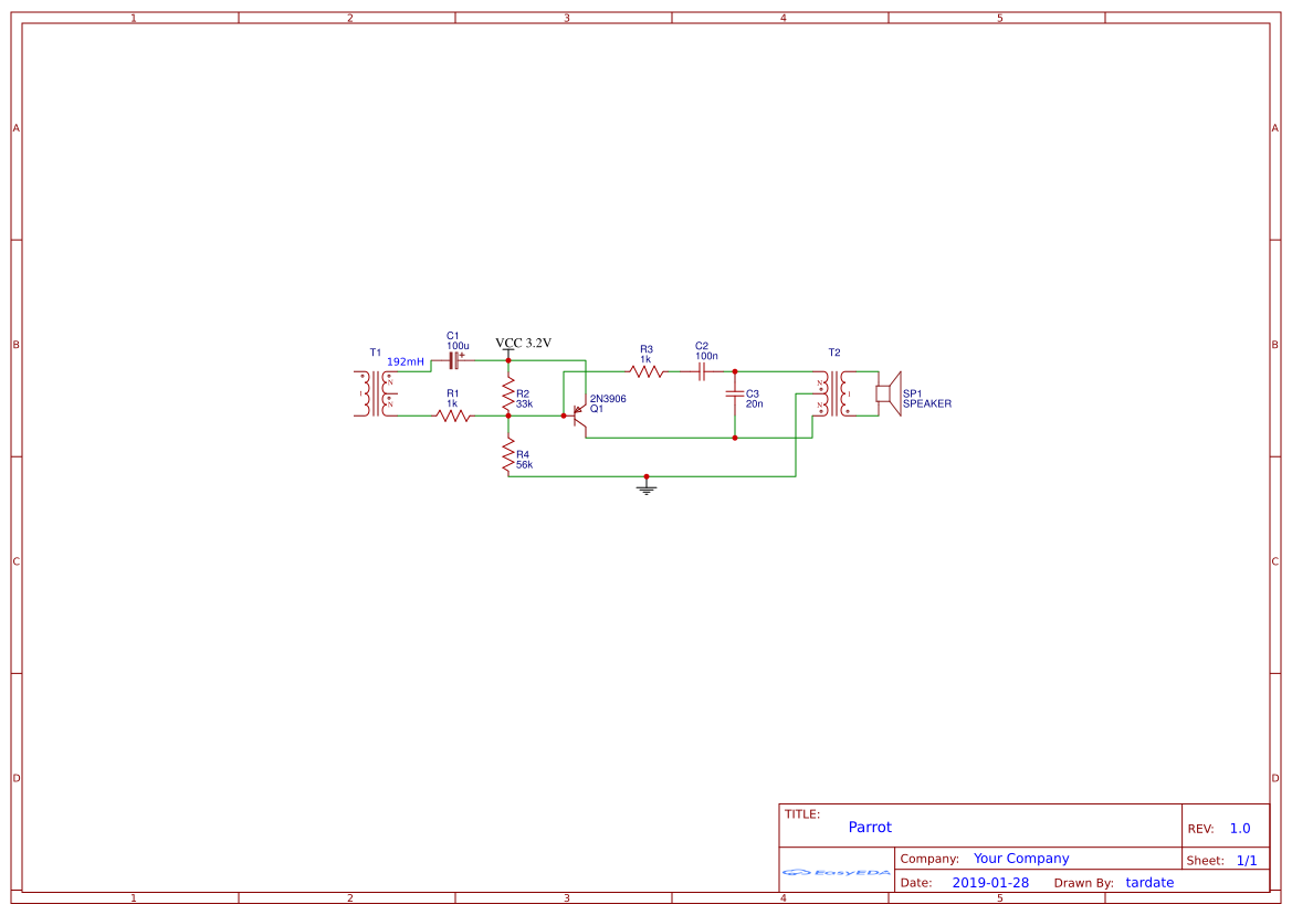
The Basic Circuit
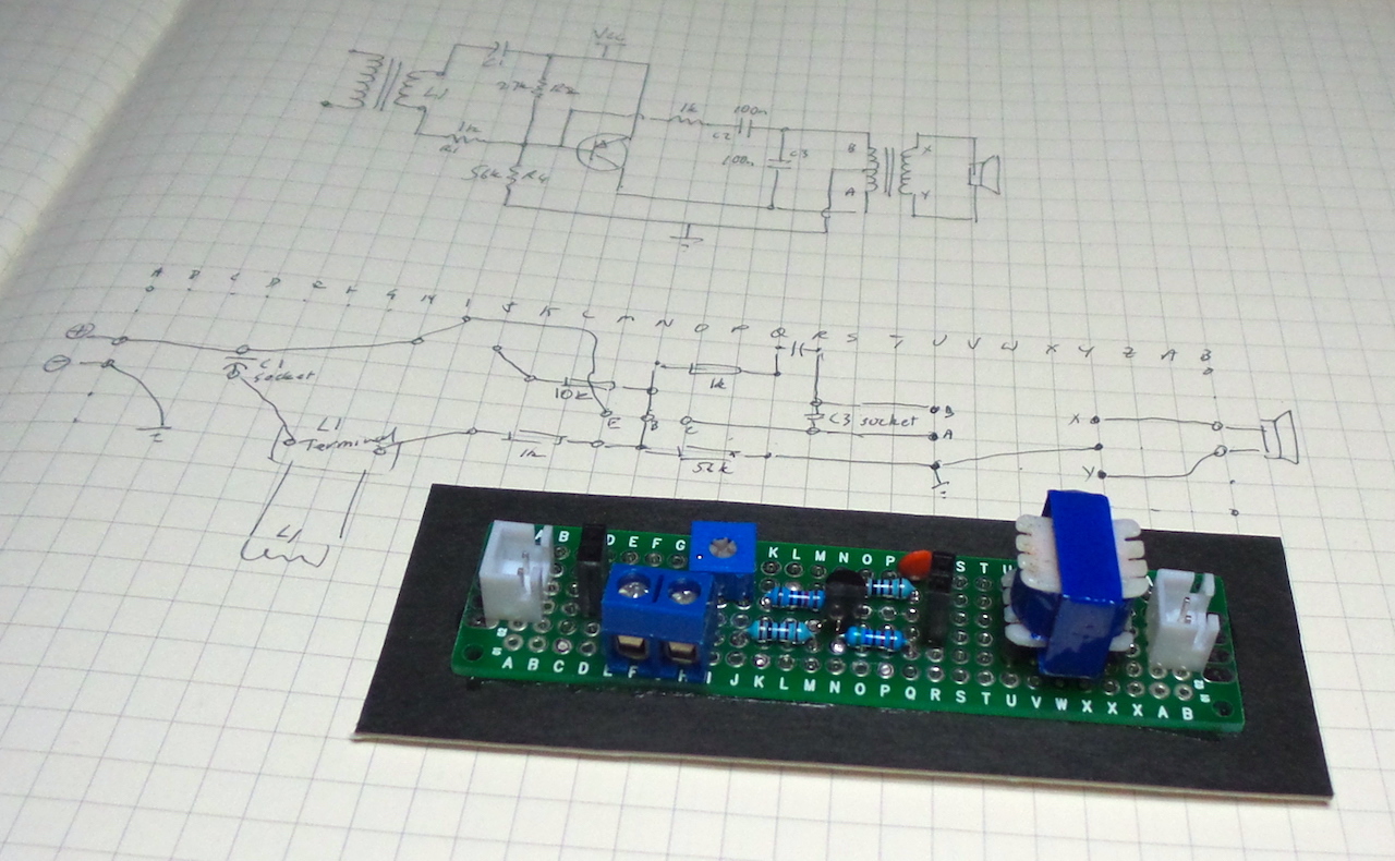
I redrew the basic schematic here in EasyEDA.
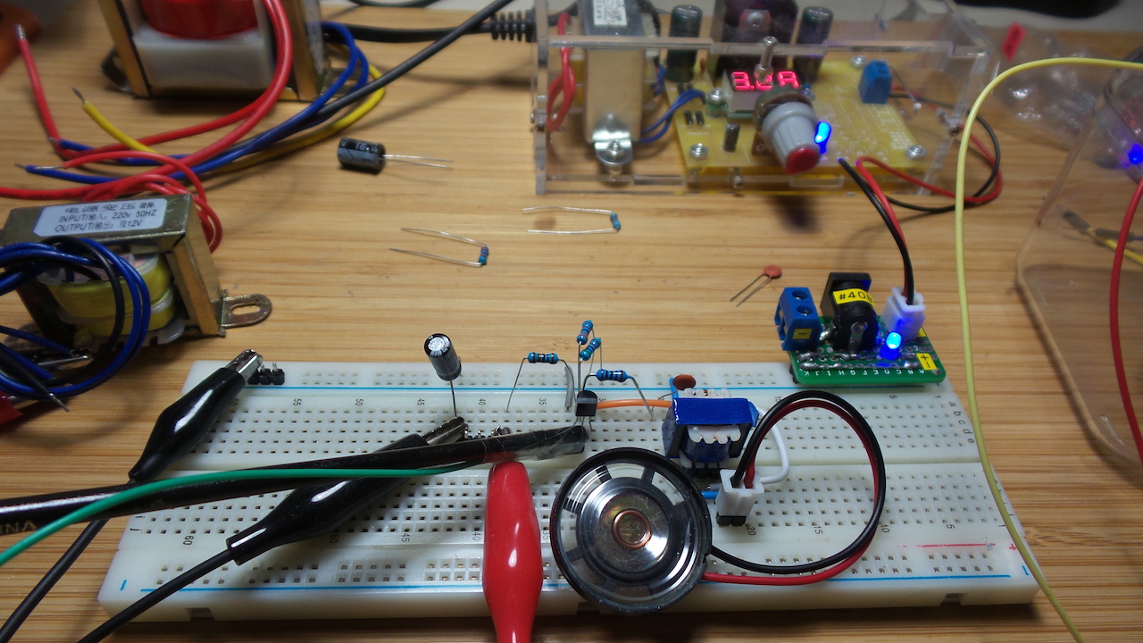
I initially built this on a breadboard to prove the circuit and experiment with component values. A wide range of values are possible, but I specifically tested with the following values:
| Component | Value |
|---|---|
| L1* | transformer winding measured at 192mH |
| C1* | 100µF |
| C2 | 100nF |
| C3* | 20nF |
| R2* | 33kΩ |
| R4 | 56kΩ |
| R1, R3 | 1kΩ |
| Q1 | 2N3906 PNP |
| VCC* | 3.3V |
NB: the components marked with a (*) are the ones most useful to change in order to achieve different effects.
How it Works
My brief take..
The L1/C1/R1 resonant circuit acts like a “spring” on the base on the PNP, which is biased with R2:R4.
The collector is coupled to effectively a a tank circuit comprising C3 and the audio transformer, with feedback to the base of the transistor via C2 and R3.
The effect of these components on the sound can be summarised in general terms:
- increasing L1/C1 will extend the sweep envelope of the “chirp” i.e. the rise and fall of each chirp.
- adjusting the bias point R2:R4 will determine the point at which the chirp cuts-off. i.e. the mark-space ratio
- C3 controls the pitch of the chirp
Also, the circuit is voltage dependant, so adjusting the supply voltage will affect the sounds produced.
The result is a series of “chirps”..
With each chirp comprising an oscillation that sweeps a range of frequencies
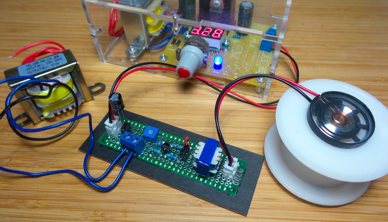
Protoboard Variation
I put the circuit on a protoboard strip with some variations:
- replaced the 27kΩ R2 bias resistor with a combination of 10kΩ resistor and 100kΩ pot to allow bias adjustment
- C1 and C3 are mounted in female pin headers for easy replacement
- L1 connected via a terminal block
Component Combinations
A wide range of “chirp” effects are possible. Here are some of the component values/ranges I’ve used successfully.
| Component | Value |
|---|---|
| L1* | transformer windings: 47mH, 70mH, 192mH |
| C1* | 100µF, 220µF, 330µF, 470µF |
| C3* | 20nF, 100nF |
| R2* | 27kΩ, 33kΩ, 10kΩ + 100kΩ pot |
| VCC* | 2.5V - 12V |
Credits and References
- bird-tone generator circuits
- Hacking Nature’s Musicians - Kelly Heaton
- Electronic Bird Sculture - Kelly Heaton’s winning entry in the Hackaday Circuit Sculpture contest
- 2N3906 datasheet
- ..as mentioned on my blog