#871 Perfect LM386 Amplifier Circuit?
Incorporating all of the best design advice to hopefully produce the best LM386 amplifier circuit possible. And it does in fact perform rather impressively.
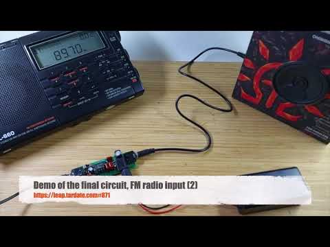
Here’s a quick demo..
Notes
The LM386 is a low-voltage, low-power audio power amplifier integrated circuit, originally developed by National Semiconductor in the mid-1970s. It operates from a single power supply, typically between 4V and 12V, and requires very few external components to produce an audio amplifier with a typical output power of up to 0.5W. Its internally configured voltage gain is 20 (26dB). The chip incorporates internal biasing, thermal protection and a bypass pin for reducing power-supply and bias-related noise.
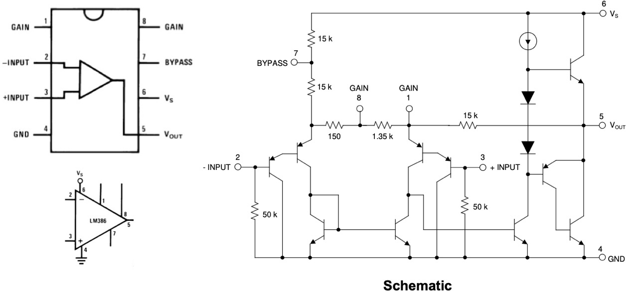
The good news about the LM386 is the component count, small size and ease of use means that the LM386 has shown up in many circuits and has been widely used in battery-powered audio devices, small radios, intercoms, portable speakers and simple guitar practice amplifiers.
The bad news is that many of those circuits are pants! Some don’t even follow the most basic recommendations in the data sheet.
So what is a “good” or even “perfect” LM386 audio amplifier circuit? Perhaps I can find all the best practices and give them a go.
That’s what this circuit is all about…
The PERFECT LM386 audio amplifier?
Enter this very informative video by JohnAudioTech: “Make the PERFECT LM386 audio amplifier?”. Some of the key takeaways..
Input stage:
- Input coupling and filter:
- AC-couple the input (C1), to ensure any incoming DC offset won’t cause clipping
- Add a low-pass filter on the input (C2)
- Don’t short the reference voltage bias resistor
- Inverting input AC-coupled to ground (C3) to avoid bypassing the internal input bias resistor
- Input volume pot is optional:
- 10kΩ audio/log for line level
- 100kΩ linear for instruments (because of internal 50kΩ pulldown)
- ground the pot case
- if the source has volume control, then it is not really needed here
- if not needed, better to leave out to avoid noise issues
Gain stage:
- Only add as much gain as required
- Line level - no additional gain required (default 20x)
- Instrument input - probably need more gain (max 200x with 10µF across pins 1-8)
- Add bypass cap on pin 7, especially with noisy power supplies
- Connecting an optional 10µF capacitor between pin 7 (bypass) and ground filters out high-frequency power supply ripple and prevents noise from entering the high-gain internal stages.
Output stage:
- Use with a suitable speaker >= 8Ω
- 4Ω load has a very poor current v voltage curve - doesn’t deliver much power to speaker
- Output coupling capacitor (C6)
- 470µF large enough, don’t need high as not expecting so much bass from this amp
- Could be lower like 200uF for guitar amp, as don’t need the bass response
General Design Guidelines:
- Use Polyester/Mylar caps for main audio path. Compared with ceramic/MLCC caps:
- extremely low audio signal distortion
- very low microphonics/noise
- high capacitance stability
- PCB layout:
- Aim for star-ground layout to avoid power and other signals on audio traces
- Power supply smoothing (C4)
- larger values don’t make much difference
- 270nF instead of 100nF per datasheet
- with a battery, not so important
- Use 9V supply:
- lower voltages such as 5V won’t deliver max power output
- unless using LM283M-3 1W (18V) variants
- Twist wires to avoid differential-mode noise
- Signal and Return: Always twist a signal wire directly with its specific ground or return wire, rather than twisting multiple unrelated signals together.
- Power and Ground: Twist positive and negative DC power lines together to contain the magnetic loop area and prevent them from radiating noise to nearby circuits.
The “Perfect” Circuit Realised
Designed with Fritzing: see Perfect386.fzz.
So let’s boil it down to an actual build. Some specific decisions I’ve made:
- 220nF for C1,C3 since that is what I have on hand. I suspect not significantly different performance than the 270nF used by JohnAudioTech
- No bypass capacitor on pin 7 since I’m using a battery power supply
- Added S1 to select between 20x and 200x gain
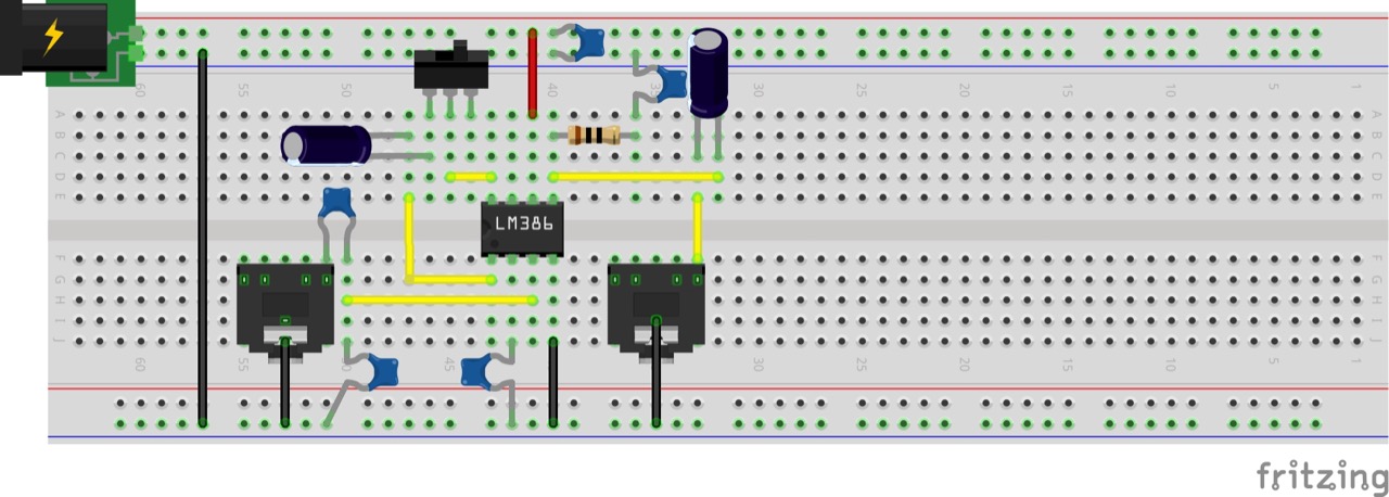
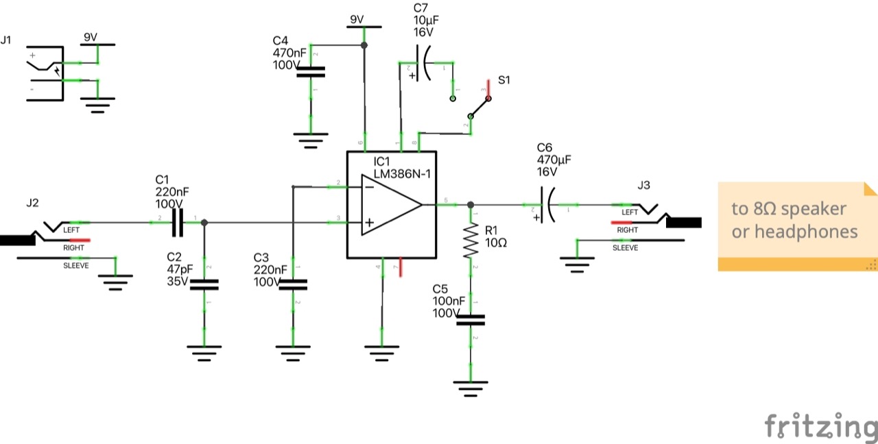
Parts:
| Ref | Qty | Item |
|---|---|---|
| IC1 | 1 | LM386N-1 IC |
| R1 | 1 | 10Ω 1/8W resistor |
| C1,3 | 2 | 220nF 100V Polyester (Mylar) film capacitor |
| C2 | 1 | 47pF ceramic capacitor |
| C5 | 1 | 100nF 100V Polyester (Mylar) film capacitor |
| C6 | 1 | 470µF 16V electrolytic capacitor |
| C7 | 1 | 10µF 16V electrolytic capacitor |
| J1 | 1 | 5.5x2.1mm barrel jack |
| J2,3 | 2 | 3.5mm stereo TRS jack |
| S1 | 1 | SPDT switch |
Breadboard Build
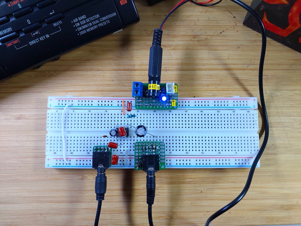
The circuit works surprisingly well even on a breadboard. For testing, I manually added or removed the 10µF gain capacitor as required.
Protoboard Build
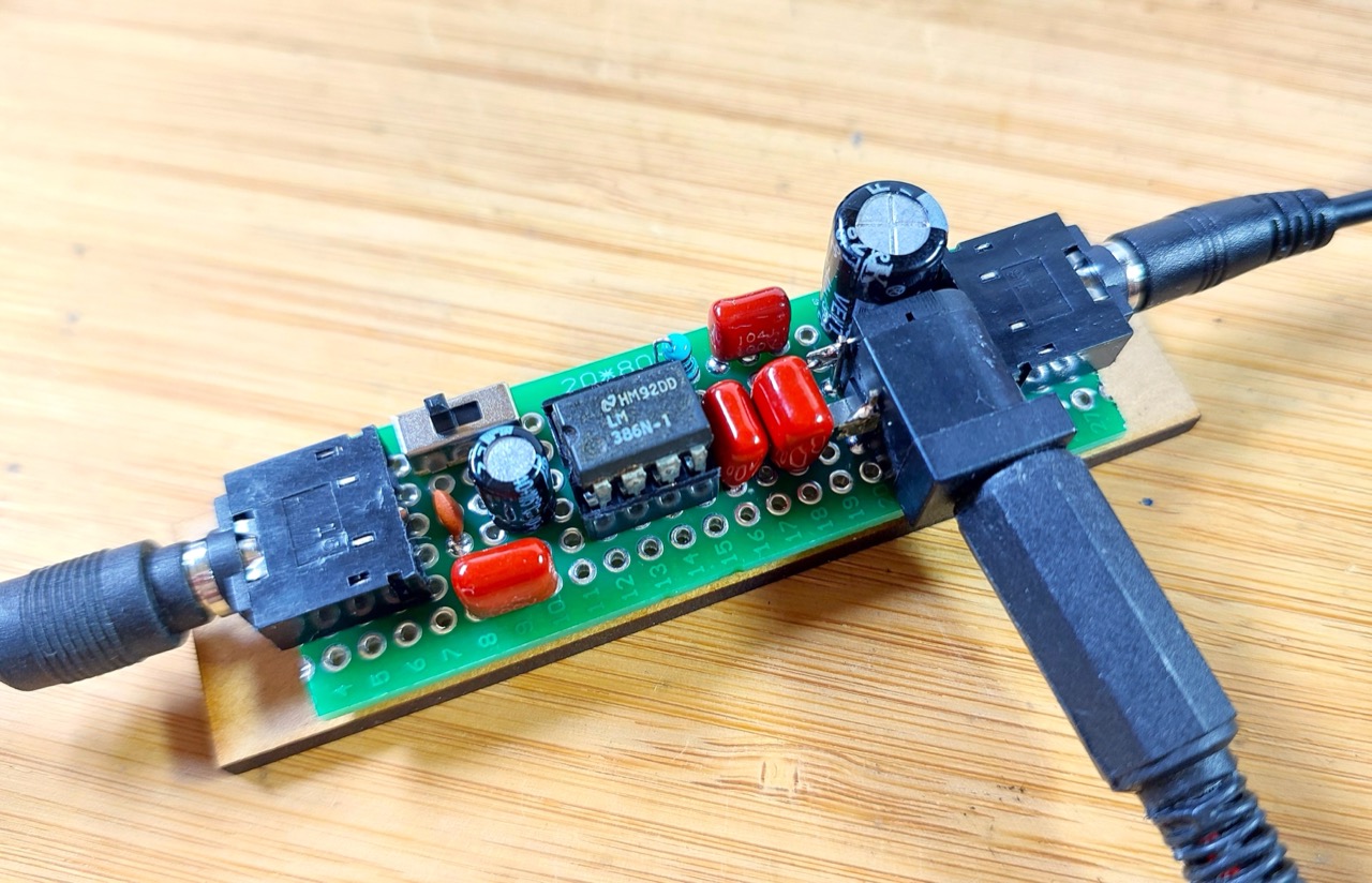
I finally transferred the circuit to a 2x8cm protoboard. This is the layout I used:
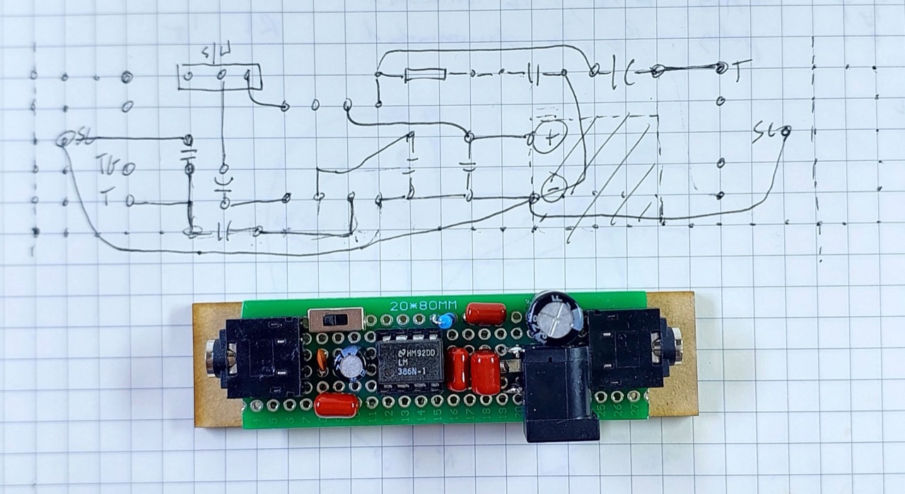
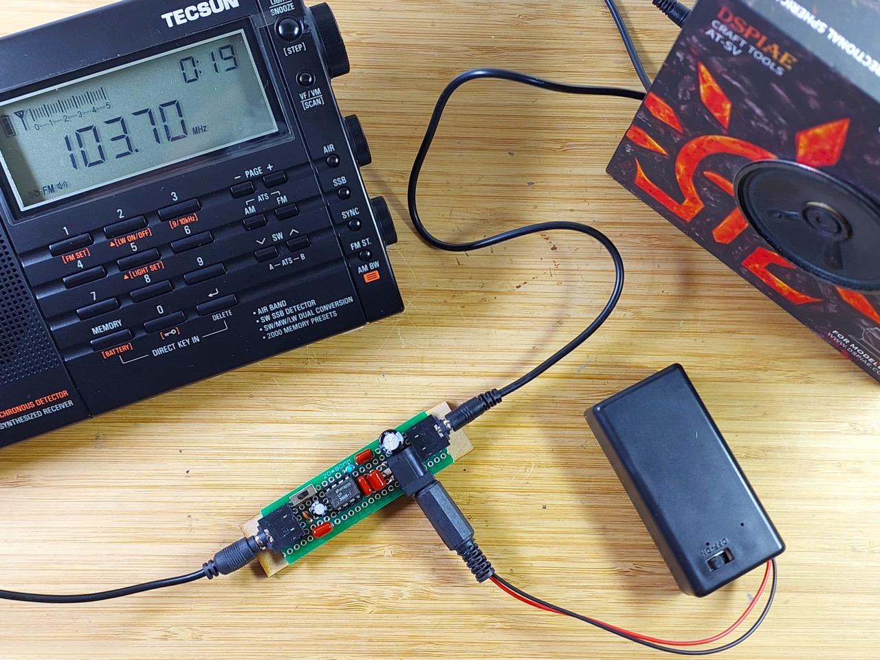
Tested with FM radio input. Works beautifully! I haven’t made any measurements of gain or harmonic distortion (yet). See JohnAudioTech’s video for the measurements he made.
Credits and References
- LM386 Product Info - TI
- LM386 datasheet
- https://hackaweek.com/hacks/the-12-watt-lm386-audio-amplifier/
- “5PCS/LOT LM386N-1 LM386N LM386 DIP-8 LM386N-3 LM386N-4” (aliexpress seller listing)
- Purchased 5x LM386N-1 from QIAOMAER electronicchip Store for S$1.70 after discounts (Nov-2026)
- “CBB Capacitor Assortment Kit 100V 10nF - 470nF 100PCS=10values*10pcs Metallized Polyester Film Capacitors KIT DIY” (aliexpress seller listing)
- Purchased 1 pack from DSSRQI Official Store for S$2.56 after discounts (Nov-2026)
Make the PERFECT LM386 audio amplifier?
YouTube by JohnAudioTech