
#549 Bare Metal C on the Blue Pill
Bare metal programming the STM32F103C8T6 (as used in the Blue Pill) by hand with gcc and the stlink open source STM32 MCU programming toolset.
Notes
The STM32F103C8T6 is an ARM Cortex-M3 processor thats very popular in cheap development boards like the Blue Pill.
Usually one would program the device with an IDE such as STM32CubeIDE, Keil, or even the Arduino IDE with STM32 extensions. Hoever, that hides much of the “fun” of programming a specific device, so here I thought I would investigate pure bare metal coding to see what it takes to get the most minimal program up and running.
I was inspired to try this after watching the bare metal embedded lecture series from Fastbit Embedded Brain Academy on YouTube. It focused on a different STM32 model, but the details of the approach were very useful for working with the STM32F103C8T6.
My goal is modest - blink the LED that’s usually attached to PC13 on most development boards.
I’m running this on MacOSX, and for tooling I’m using:
- GNU Arm Embedded Toolchain - C compiler, linker, gdb debugger
- ST-Link/V2 programmer - simple USB attachment to the SWD pins on the development board
- stlink - open source STM32 MCU programming toolset for flashing the device and running a debug host if required.
Note that all the details that follow are specific to the STM32F103C8T6. The specifics may vary (a lot) for other STM32 models.
Bare Metal Programming Overview
- write the main C program. I am not using any C standard library functions so far, which simplifies the linking process. The program comprises:
- blinky.c/h - the main program
- led.c/h - all the functions to enable and blink the LED on GPIO PC13
- delay.c/h - a simple delay function that approximates a millisecond-resolution
- implement the start up code - see stm32_startup.c
- defines the ISR vector map and implements the main reset handler
- the reset handler sets up memory for execution then hands over control to the main program
- write the linker script stm32_ls.ld which defines where all the code pieces should be assembled in memory
- compile and link everything with gcc
- use objcopy to produce the binary image to be flashed on the device
- use the stlink tools to flash the device
- optionally, fire up st-util and gdb to debug the program on the device
All the steps are automated with a Makefile.
About the STM32F103C8T6
To program bare metal, it’s necessary to know the precise hardware details, in particular the memory map and register definitions. The two critical resources I’ve used for this can be obtained from the STM32F103 product info page:
- DS5319: STM32F103x8/B datasheet
- RM0008: STM32F103xx (etc) reference manual
Some of the main details follow..
Device overview from datasheet section 2.1
| Feature | STM32F103C8T6 |
|---|---|
| Flash | 64 Kbytes |
| SRAM | 20 Kbytes |
| Timers - general purpose | 3 |
| Timers - advanced control | 1 |
| Communication - SPI | 2 |
| Communication - I2C | 2 |
| Communication - USART | 3 |
| Communication - USB | 1 |
| Communication - CAN | 1 |
| GPIOs | 37 |
| 12 bit ADC | 2 |
| ADC channels | 10 |
| CPU Frequency | 72 MHz |
| Operating Voltage | 2.0 to 3.6 V |
| Operating Temperature | –40 to 85 °C |
| Package | LQFP48 |
STM32F103C8T6 (numbering scheme from datasheet section 7):
- STM32 = ARM-based 32-bit microcontroller
- F = Product type: general-purpose
- 103 = Device subfamily: performance line
- C = Pin count: 48 pins
- 8 = Flash memory size: 64 Kbytes of Flash memory
- T = Package: LQFP
- 6 = Industrial temperature range, –40 to 85 °C.
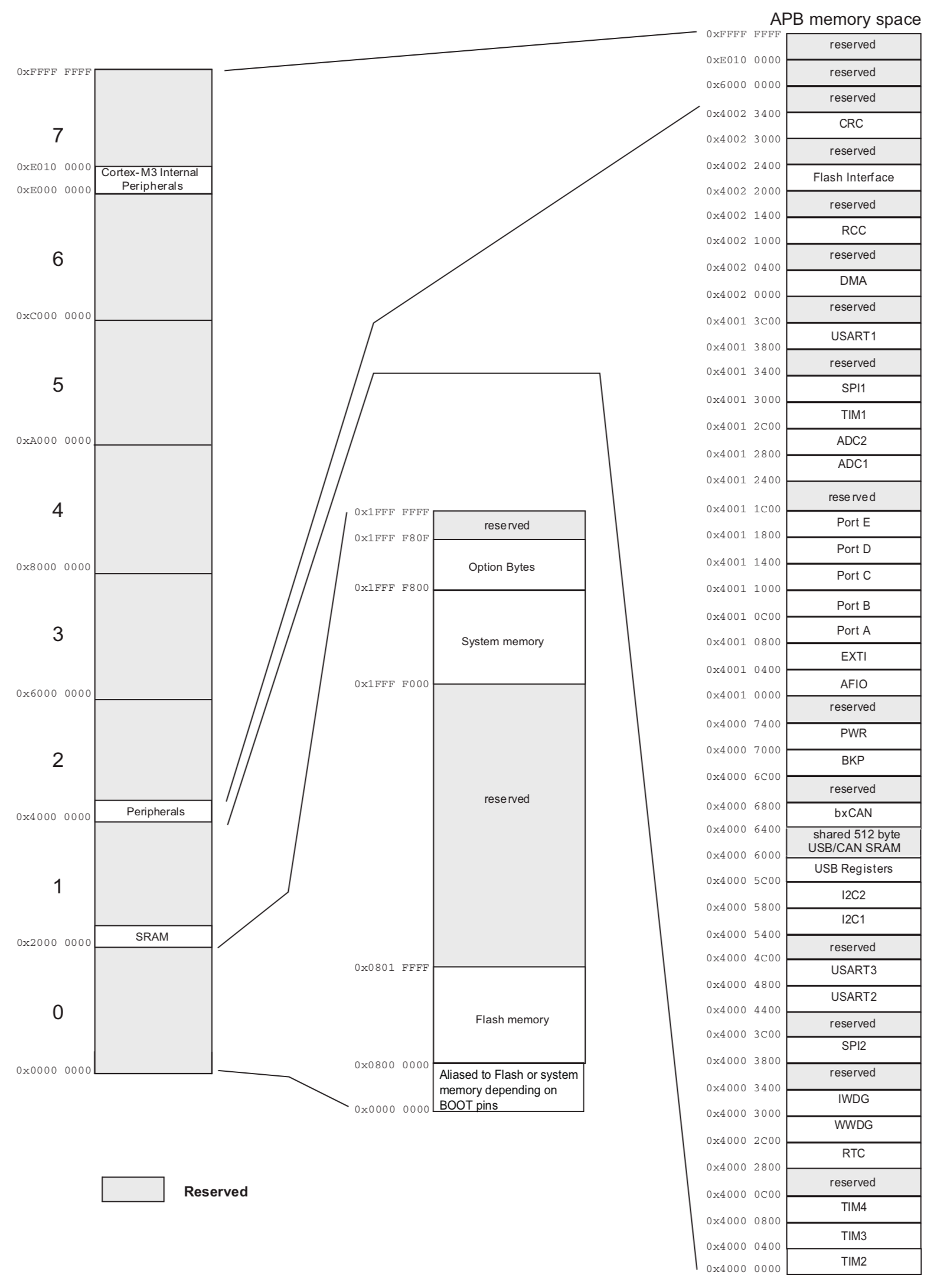
Memory Map
Memory map from datasheet section 4:
Interrupt Vectors
STM32F103C8T6 is classified by ST as a “Medium-density performance line” device.
Interrupt and exception vectors are detailed in RM0008 10.1.2, Table 63: Vector table for other STM32F10xxx devices.
The details were used to create the isr vector table in stm32_startup.c
Linker Script
The linker script stm32_ls.ld is used to define three critical details for the linker:
ENTRY- the function used as the program entry pointMEMORY- the device-specific memory regions. We care about two: FLASH and SRAM.SECTIONS- how program code is collected into memory regions
GPIO
For this example, I’m just going to control GPIO on PC13. This is pin 2 on the LQFP48 package, and usually connected to an on-board LED on most development boards.
During and just after reset, the alternate functions are not active and the I/O ports are configured in Input Floating mode (CNFx[1:0]=01b, MODEx[1:0]=00b). When configured as output, the value written to the Output Data register (GPIOx_ODR) is output on the I/O pin.
It is possible to use the output driver in Push-Pull mode or Open-Drain mode. I’m going to use Push-Pull mode, so that it doesn’t matter whether the LED is wired to source or sink from the pin.
Note:
- whether the LED is wired to source or sink from PC13 will determine if the pin logic is active high or low
- the current handling of PC13 is very limited (+/-3mA) but I trust that the development board makers have sized the LED current limiting resistor accordingly.
There are four steps required to drive a GPIO pin output:
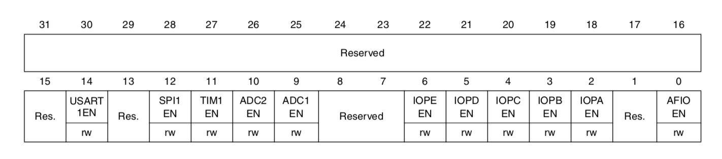
- The GPIO port clock must be enabled for anything to work (RCC_APB2ENR register)
- the GPIO pin configuration must be set correctly (GPIOCx_CRH or GPIOCx_CRH registers depending on the port and pin in question)
- the GPIO pin mode must be set correctly (GPIOCx_CRH or GPIOCx_CRH registers depending on the port and pin in question)
- finally, the output value can be set in the GPIOx_ODR register
For PC13 - GPIO port C, bit 13 - these are the specifics, found in the RM0008 STM32F103xx (etc) reference manual:
Reset and clock control RCC:
- Memory region: 0x4002 1000 - 0x4002 13FF
- RCC_APB2ENR is at offset 0x18: 0x4002 1018
- IOPCEN is bit 4 of RCC_APB2ENR: I/O port C clock enable. Set to 1 for I/O port C clock enabled
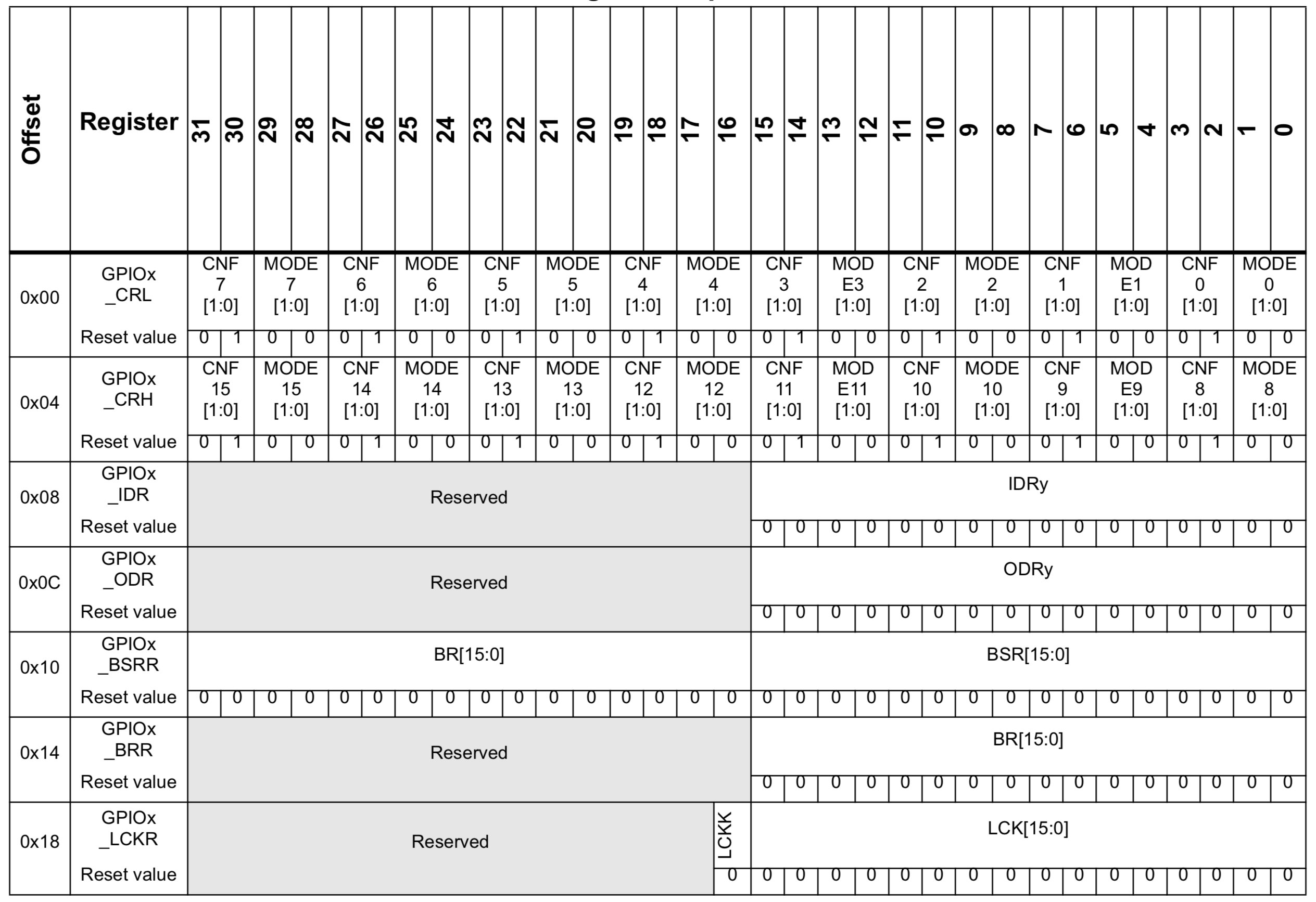
GPIO Port C:
- Memory region: 0x4001 1000 - 0x4001 13FF
- GPIOC_CRH is at offset 0x4: 0x4001 1004
- PC13 configuration is set with CNF13[1:0] in GPIOC_CRH
- Possible CNFx values when the port is set for output:
- 00: General purpose output push-pull
- 01: General purpose output Open-drain (reset state)
- 10: Alternate function output Push-pull
- 11: Alternate function output Open-drain
- PC13 mode is set with MODE13[1:0] in GPIOC_CRH. Possible values:
- 00: Input mode (reset state)
- 01: Output mode, max speed 10 MHz.
- 10: Output mode, max speed 2 MHz.
- 11: Output mode, max speed 50 MHz
- GPIOC_ODR is at offset 0xC: 0x4001 100C
- sets the output data value, 1 bit per pin.
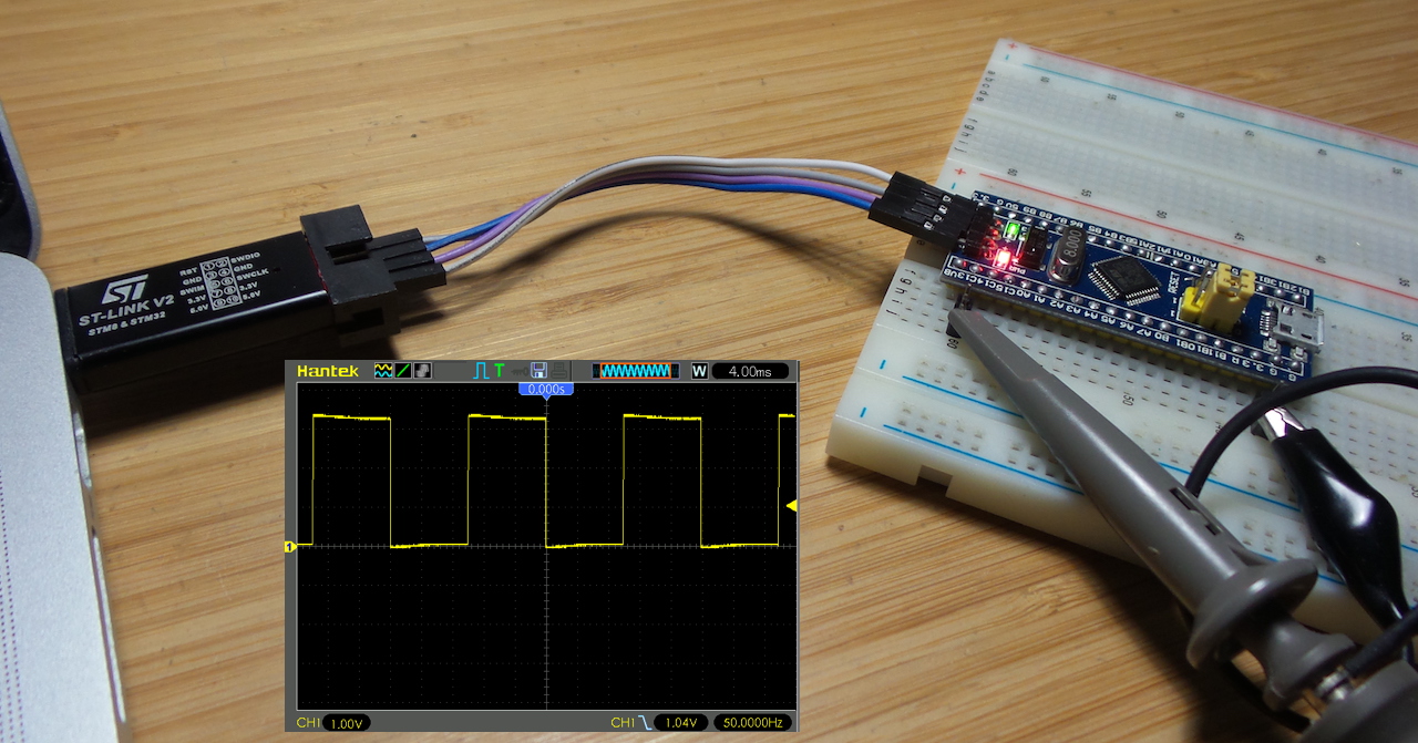
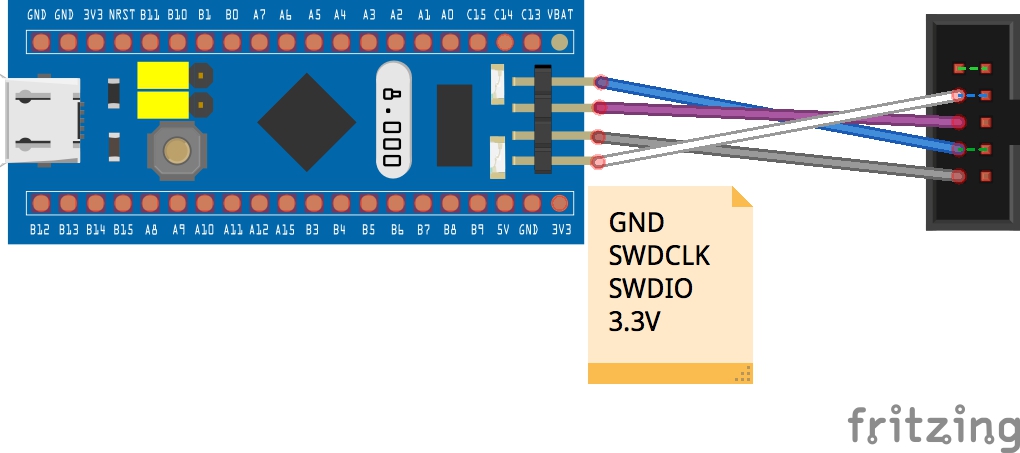
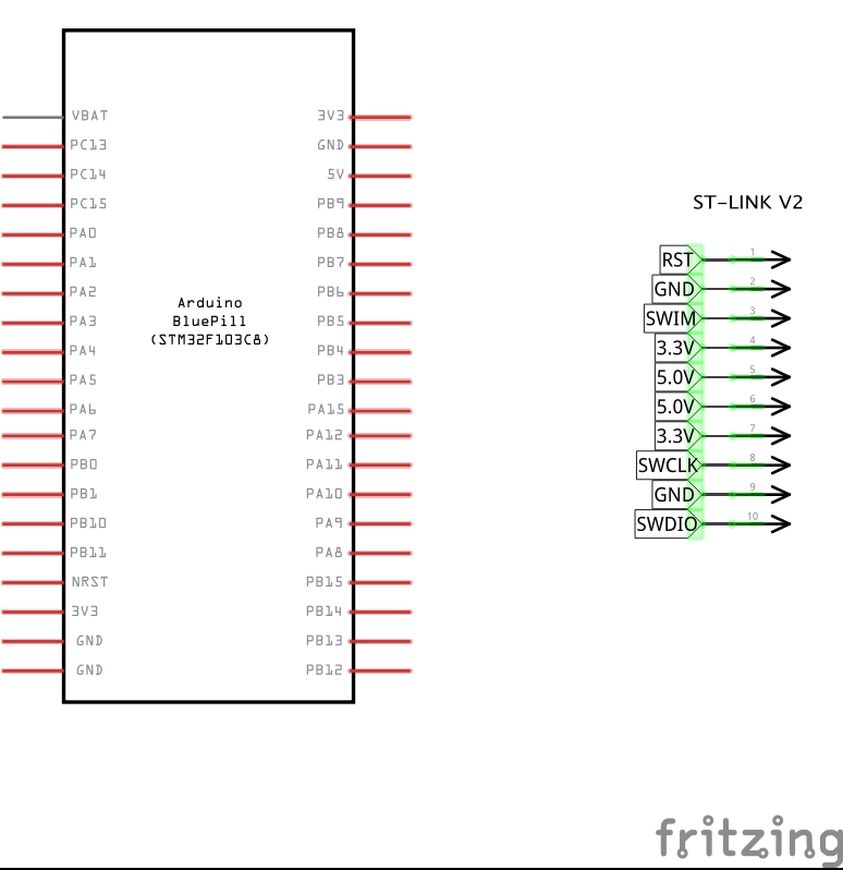
Connecting the Programmer
The ST-Link/V2 programmer connects to the SWD header on the module. Only 4 pins need to be connected from the 10-pin shroud on the programmer: 3.3V, GND, SWDIO, SWDCLK
Building the project
Default make or make all will just compile. make flash compiles as needed and flashes the device with st-flash:
$ cd blinky
$ make flash
arm-none-eabi-gcc -c -mcpu=cortex-m3 -mthumb -std=gnu11 -Wall -g -O0   -c -o blinky.o blinky.c
arm-none-eabi-gcc -c -mcpu=cortex-m3 -mthumb -std=gnu11 -Wall -g -O0   -c -o delay.o delay.c
arm-none-eabi-gcc -c -mcpu=cortex-m3 -mthumb -std=gnu11 -Wall -g -O0   -c -o led.o led.c
arm-none-eabi-gcc -c -mcpu=cortex-m3 -mthumb -std=gnu11 -Wall -g -O0   -c -o stm32_startup.o stm32_startup.c
arm-none-eabi-gcc -T stm32_ls.ld -nostdlib -Wl,-Map=blinky.map -o blinky.elf blinky.o delay.o led.o stm32_startup.o
arm-none-eabi-objcopy -O binary blinky.elf blinky.bin
st-flash write blinky.bin 0x08000000
st-flash 1.6.0
2020-05-07T20:00:56 INFO common.c: Loading device parameters....
2020-05-07T20:00:56 INFO common.c: Device connected is: F1 Medium-density device, id 0x20036410
2020-05-07T20:00:56 INFO common.c: SRAM size: 0x5000 bytes (20 KiB), Flash: 0x10000 bytes (64 KiB) in pages of 1024 bytes
2020-05-07T20:00:56 INFO common.c: Attempting to write 708 (0x2c4) bytes to stm32 address: 134217728 (0x8000000)
Flash page at addr: 0x08000000 erased
2020-05-07T20:00:56 INFO common.c: Finished erasing 1 pages of 1024 (0x400) bytes
2020-05-07T20:00:56 INFO common.c: Starting Flash write for VL/F0/F3/F1_XL core id
2020-05-07T20:00:56 INFO flash_loader.c: Successfully loaded flash loader in sram
  1/1 pages written
2020-05-07T20:00:56 INFO common.c: Starting verification of write complete
2020-05-07T20:00:56 INFO common.c: Flash written and verified! jolly good!
Calibrating the Delay
The delay function used in the program is not timer based - it just does a NOP loop for an appropriate number of cycles.
I changed the program to use a 10ms delay between on and off transitions, used a scope to measure the resulting waveform, and then calcualted what the correct number of loops per millisecond should be. An alternative approach would be to disassemble the code and count the operations and operation timing, but this was quicker!
At 10ms per transition (20ms full cycle), we should see a 50Hz square wave. Hooking up to an oscilloscope, that’s exactly what I’m recording:
Debugging with GDB
The makefile is set to build the project with debug symbols, so inspecting program operation with gdb is made a little easier.
Running st-util in one terminal window:
$ make debughost
st-util
st-util 1.6.0
2020-05-07T23:23:51 INFO common.c: Loading device parameters....
2020-05-07T23:23:51 INFO common.c: Device connected is: F1 Medium-density device, id 0x20036410
2020-05-07T23:23:51 INFO common.c: SRAM size: 0x5000 bytes (20 KiB), Flash: 0x10000 bytes (64 KiB) in pages of 1024 bytes
2020-05-07T23:23:51 INFO gdb-server.c: Chip ID is 00000410, Core ID is  1ba01477.
2020-05-07T23:23:51 INFO gdb-server.c: Listening at *:4242...
2020-05-07T23:24:39 INFO gdb-server.c: Found 6 hw breakpoint registers
2020-05-07T23:24:39 INFO gdb-server.c: GDB connected.
...
Then connecting with gdb. Here’s a session where I break on the led_on function and examine the effect on the GPIOC_ODR register:
$ make gdb
arm-none-eabi-gdb blinky.elf
GNU gdb (GNU Tools for Arm Embedded Processors 9-2019-q4-major) 8.3.0.20190709-git
Copyright (C) 2019 Free Software Foundation, Inc.
License GPLv3+: GNU GPL version 3 or later <http://gnu.org/licenses/gpl.html>
This is free software: you are free to change and redistribute it.
There is NO WARRANTY, to the extent permitted by law.
Type "show copying" and "show warranty" for details.
This GDB was configured as "--host=x86_64-apple-darwin10 --target=arm-none-eabi".
Type "show configuration" for configuration details.
For bug reporting instructions, please see:
<http://www.gnu.org/software/gdb/bugs/>.
Find the GDB manual and other documentation resources online at:
    <http://www.gnu.org/software/gdb/documentation/>.

For help, type "help".
Type "apropos word" to search for commands related to "word"...
Reading symbols from blinky.elf...
(gdb) target extended localhost:4242
Remote debugging using localhost:4242
Reset_Handler () at stm32_startup.c:179
179 void Reset_Handler(void) {
(gdb) break led_on
Breakpoint 1 at 0x800021e: file led.c, line 27.
(gdb) cont
Continuing.
Note: automatically using hardware breakpoints for read-only addresses.

Breakpoint 1, led_on () at led.c:27
27    uint32_t *pGPIOC_ODR = (uint32_t *)GPIOC_ODR;
(gdb) list
22
23    led_off();
24  }
25
26  void led_on(void) {
27    uint32_t *pGPIOC_ODR = (uint32_t *)GPIOC_ODR;
28    *pGPIOC_ODR |= ( 1 << PC13);
29  }
30
31  void led_off(void) {
(gdb) next
28    *pGPIOC_ODR |= ( 1 << PC13);
(gdb) x/x pGPIOC_ODR
0x4001100c: 0x00000000
(gdb) next
29  }
(gdb) x/x pGPIOC_ODR
0x4001100c: 0x00002000
(gdb) info breakpoints
Num     Type           Disp Enb Address    What
1       breakpoint     keep y   0x0800021e in led_on at led.c:27
  breakpoint already hit 1 time
(gdb) delete 1
(gdb) cont
Continuing.
Credits and References
- STM32F103 product info
- ST-Link/V2 programmer
- stlink
- GNU Arm Embedded Toolchain
- gdb
- gdb cheat sheet
- Bare metal embedded lecture series - Fastbit Embedded Brain Academy