
#476 Simplest Direct FM Receiver
Taming a very simple direct conversion FM receiver.

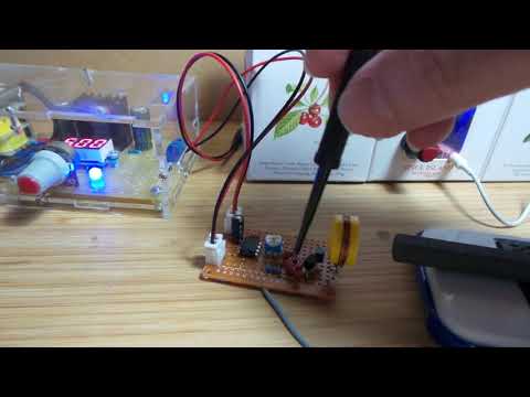
Here’s a quick demo..
Notes
I’ve actually had “build a simple FM receiver” in my WIP bucket for years (literally). I could never get a decent enough result to call the project “done”, so it always went back on the shelf for another look, another day..
Well, I had another shot at it today and finally (with the help of an LCR45 and inspiration from Lechoslowianin ) I’m finally able to get this show on the road!
Two important factors for success:
- appropriately sizing the coil in the resonant tank circuit.
- selecting an appropriate operating voltage
Background
The most basic version of a simple direct conversion FM radio is covered in 3.15.1 of Mikroelektronika’s excellent online book “Radio Receivers, from crystal set to stereo”.
Many variations of this circuit are available around the web, often with the addition of an LM386 amplifier stage, such as this design on electronicsforu.
There are a number of YouTube videos of builds, demonstrating a wide degree of success.
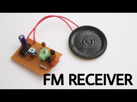
One of the first I found that demonstrated decent results was “How to make FM Radio receiver at home” by RJ Imagination:
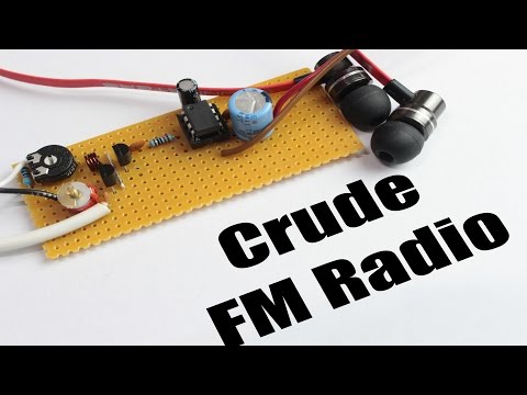
Great Scott built a version but didn’t get great results:
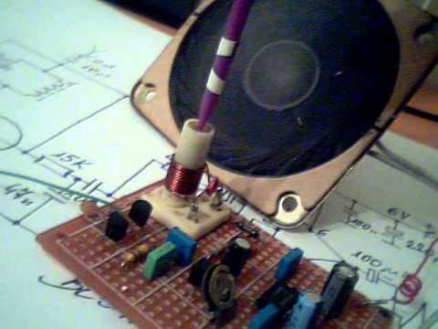
The best version I’ve seen is perhaps the build by Lechoslowianin, “Proste radio FM jak zrobić”:
Construction
The basic design I’m using here is from Mikroelektronika’s 3.15.2 The Simplest FM Receiver with Audio Amplifier.
My first builds following the schematic exactly were spectacularly unsuccessful:
- weak signal lost in the noise (if any signal at all)
- virtually no selectivity
After much experimentation, the lessons learned..
If there is no signal at all, the operating voltage may be swamping the tank circuit:
- R1 drops the battery voltage to tank circuit.
- I had no success at all with the 9V battery and R1=10kΩ shown on many schematics.
- Try lower voltage or increasing R1… this circuit works well down to around 3V
The sweet spot I settled on was 5V supply and R1=22kΩ
If the signal is weak and there is no selectivity:
- then one is probably tuning on a mess of harmonics/mirror images, not the actual signal
- the inductor L1 is very wrong.
I finally started to get good results with a 4 turn, 17mm diameter coil of 0.4mm enamelled wire. According to my LCR meter, this measures at around 0.55µH - much higher than the ~0.1µH I was getting with the coil I wound according to original instructions.
Given the variable capacitor I’m using ranges from about 5pF to 22pF, that theoretically gives me a tuning range of 45.8 MHz to 96.0 MHz (that’s a bit on the low side for the broadcast FM range, but I’ll have a shot at shifting the range later).
That corresponds to the performance I’m seeing - able to pick up all stations up to around 97.4 MHz very clearly.

One difference between various designs is the positioning of the variable capacitor - some have it in series with the coil and going to ground, some have it in parallel going to the positive rail. I tried both combinations, with the final “good” circuit using the parallel arrangement (maybe it would work just as well going to ground, but I haven’t testing it).
Even though I have relatively strong FM broadcast signals in my area, I found an antenna indispensable. I added 60cm of random wire, with a 10pF coupling capacitor.
One other variation in my circuit was the choice of transistor. The circuits that reportedly work well are using either the BF494 or BF199 NPN transistors - both obsolete products and marketed as an “RF Transistors” with gain bandwidth product over 1100 MHz. A good substitution is perhaps 2N5109 with a 1200MHz gain bandwidth product. I don’t have any 2N5109’s, so I’ve simply used S9014 with only a 270MHz gain bandwidth product, although of the stock I have on hand, an S9018 (800 MHz) might have been a better choice.
Final Construction
The final circuit I used is as follows:

Although I didn’t build on a breadboard, this is what it could look like (stray capacitance may make this difficult):

The layout I used for the protoboard build:

Under test.. the variable capacitor is good for rough adjustment but for fine control it is much easier to adjust the inductor with a bit of ferrite core.

Credits and References
- 3.15.1 The Simplest FM Receiver - Radio Receivers, from crystal set to stereo
- 3.15.2 The Simplest FM Receiver with Audio Amplifier - Radio Receivers, from crystal set to stereo
- Simple FM Receiver - electronicsforu
- Small FM Radio Circuit
- Lechoslowianin, “Proste radio FM jak zrobić”