
#464 Single Transistor AM Transmitter
Building a low power, single transistor AM transmitter with surprisingly good fidelity.

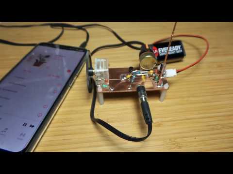
Here’s a quick demo..
Notes
Building AM receivers is very good practice for understanding the technology of radio, however since we no longer have any local AM broadcasts it can be a challenge to verify that things are indeed working correctly.
This is where low-power AM transmitters can be very useful.
I found a one transistor AM transmitter design posted on YouTube by Stefan0719, and this was the starting point and inspiration for my experimentation.
I first experimented with the same circuit on a breadboard, and it worked surprisingly well.

Circuit Design
While the original circuit worked quite well off the bat, it did not do a very good job of attenuating harmonic content. I’ve added additional filtering on the output and harmonics are now tamped down quite significantly (the C7,L2,C8 T-filter).
The original design of the carrier oscillator had C3 in series with L1 and a variable capacitor. The downside to this arrangement was significant distortion of the carrier wave outside of a “sweet spot” of tuning. In the final build I’ve moved the variable capacitor in parallel with the fixed capacitor C3 and adjusted the values somewhat. This produces a carrier tuning range of 819.49kHz to 1580.96kHz with minimal distortion across the range.
Since there’s no effective output amplification, the signal is quite weak and can only be received within a range of 30cm or so.


Ugly Build
Since things were going quite well on a breadboard, I transferred to some copper PCB stock for a more stable experimental platform.
The antenna is just a random length of copper (about 20cm). I don’t need (or want) this to be an efficient transmitter - just enough to get across the room for demonstration purposes. Stefan0719 used a standard medium-wave antenna coil with ferrite core in his build.

Testing - Carrier
Testing the carrier with the modulation input disconnected.
With the component values as given in the schematic, I’m seeing a carrier wave tuning range of 819.49kHz to 1580.96kHz. The carrier is very close to a pure sine wave at the higher frequencies, and only minor distortion at the lower end.
Interestingly, there is a resonant spot at around 1453.62kHz where the output peaks at 17.2V peak-peak (with a 9V battery).
Running at minimum carrier frequency, note the somewhat skewed sine wave. The scope trace on CH1 is captured at the output/antenna (safe-ish since this is only a low-power circuit):

The spectrum shows just the first harmonic having much power. Prior to adding the output filter network, 2nd, 3rd and 4th etc harmonics were quite prominent.

At maximum carrier frequency, the output is very close to pure sine wave.

The spectrum confirms that virtually all harmonic content has been eliminated:

Testing - With Modulation
I ran some tests with a 1kHz sine wave input. The modulation is very clean, as can be seen from the peak scope trace below.
The modulation is unbalanced, favouring the high-side of the wave. This is to be expected given the circuit design, where the modulating signal is primarily pulling down the positive bias of Q1. The placement of the variable resistor R1 provides limited scope to adjust the bias point and even out the modulation of the carrier.

Some Real Testing
Here’s some video from the bench, where I’m testing both the performance of the transmitter, but also an HX108-2 AM Receiver built from a kit, with a commercial Tecsun receiver as a benchmark.
