
#532 PIC16F84A Blinky
A quick test of programming a PIC16F84A on a breadboard and 3rd party dev board with MPLAB X (assembler). Updated 2026 for PIC-as and latest IDE tools while still using the old PICkit 3.

Here’s a quick demo..
Notes
I’m planning to play around a bit more with low-end (8 bit) PICs. To start I’d like to get my toolchain setup and testing. So for this project I’m programming a PIC16F84A-04 with a simple assembler “LED blinky” routine in order to test my setup and the following tools:
- MPLAB X IDE
- PICkit 3 (clone)
- PIC16F84A-04 on a breadboard
- PIC16F84A-04 on a 3rd party development/programming board
I originally ran this exercise in 2017 with MPLAB X IDE v5.30 and mpasm 5.86, but now updated in Feb-2026:
- Revised assembler code to use PIC-as instead of old mpasm syntax.
- Compiled with MPLAB X IDE v6.20 on macOS
- Programmed using the PICkit 3 on Ubuntu with MPLAB X IPE v6.20 (the last version to support PICkit 3)
See LEAP#331 Getting Blinky with PIC Assembler for more details on the trials and tribulations of trying to continue to use the PICkit 3 on macOS.
PIC16F84A Specs
The microchip site has plenty of info and datasheets for the processor. The core specs:
- 1024 words flash memory
- 68 bytes SRAM
- 64 bytes EEPROM
- 13 I/O ports
- 1 8-bit timer/counter
- voltage range: 2.0-5.5
- up to 4 MHz oscillator (PIC16F84A-04 variant) or 20 MHz (PIC16F84A-20 variant)

Compiling the Project with the the MPLAB X IDE
The PIC16F84ABlinky.X project is a simple single-file program in assembler that blinks an LED on pin RA3 (2) at about 4Hz.
Project settings selected as follows:
- Family: Mid-Range 8-bit MCUs (PIC10/12/16/MCP)
- Device: PIC16F84A
- Compiler: PIC-as
The configuration bits are set:
config "FOSC" = HS: HS oscillator selected (I’m going to use a 4MHz crystal)config "WDTE" = OFFwatchdog timer disabledconfig "PWRTE" = OFFpower-up timer disabledconfig "CP" = OFFcode protection disabled
Programming
I am still using an old PICkit 3 programmer: “pickit 3 Programming / emulator + PIC microcontroller / minimum system board / development board / universal programmer seat” (aliexpress seller listing) purchased for US $18.85 (Feb-2017). Only 5 of the pins are relevant for programming the PIC16F84A:
| PIC16F84A Pin | Programmer Pin | Function | Description |
|---|---|---|---|
| MCLR (4) | VPP (1) | VTEST MODE | Program Mode Select |
| VDD (14) | VDD (2) | VDD | Power Supply |
| VSS (5) | GND (3) | VSS | Ground |
| RB7 (13) | PGD (4) | DATA | Data Input/Output |
| RB6 (12) | PGC (5) | CLOCK | Clock Input |
Notes:
- MCLR is the Master Clear (Reset) input/programming voltage input. This pin is an active low RESET to the device
- In the PIC16F8X, the programming high voltage is internally generated. To activate the Programming mode, high voltage needs to be applied to MCLR input. Since the MCLR is used for a level source, this means that MCLR does not draw any significant current.
On Windows or Ubuntu, the PIC16F8X can be easily programmed using the MPLAB X IDE v6.20 or MPLAB IPE v6.20 support for the PICkit 3.
Since I am no longer able to get the PICkit 3 working with macOS, I am driving it remotely connected to an Ubuntu machine running MPLAB IPE v6.20, using the ipe-remote.sh script from LEAP#331 Getting Blinky with PIC Assembler.
$ ../GettingBlinky/ipe-remote.sh ronda-u1 16F84A PIC16F84ABlinky.X/dist/default/production/PIC16F84ABlinky.X.production.hex
PIC16F84ABlinky.X.production.hex                                                                                                                                                                 100%  216    42.4KB/s   00:00
DFP Version Used : PIC16Fxxx_DFP,1.6.156,Microchip
*****************************************************
Connecting to MPLAB PICkit 3...
Currently loaded firmware on PICkit 3
Firmware Suite Version.....01.56.09
Firmware type..............Midrange
Programmer to target power is enabled - VDD = 4.750000 volts.
Target device PIC16F84A found.
Device Revision ID = 0
Erasing...
Erase successful
Device Erased...
Programming...
The following memory area(s) will be programmed:
program memory: start address = 0x0, end address = 0x3ff
configuration memory
Programming/Verify complete
PICKIT3 Program Report
2026-02-06, 19:59:03
Device Type:PIC16F84A
Program Succeeded.
PK3 Verify Report
2026-02-06, 19:59:03
Device Type:PIC16F84A
The following memory areas(s) will be verified:
program memory: start address = 0x0, end address = 0x3ff
configuration memory
EEData memory
User Id Memory
Verification successful.
Verify Succeeded.
Operation Succeeded
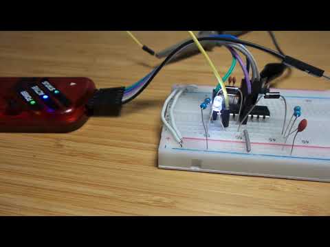
Construction
This is a minimal circuit - the application is basically a single LED on RA3. More interesting details in the schematic are the in-circuit programming connections.
Diodes D1 and D2 prevent interference between programming power (VPP) and the pull-up to VDD required to enable the chip for normal operation. Note:
- the PIC ICSP Guide does not include D2, but I found that without it I could not get the PIC to run with the programmer connected. This may be due to a difference between the clone PICkit 3 I have and the real thing.


Running on a breadboard:
Scope trace of the generated LED control signal - bang on 4 Hz:

Using the Dev Board
After successfully programming on a breadboard, I tried the dev board that I received with the PICKit 3. It turns out to be marginally more convenient, mainly because:
- the zif socket reduces the chance of damaging the PIC
- it has a pull-up resistor, and an LED with current-limiting resistor that can be used if needed
However, two limitations:
- because it is designed to generically handle any PIC up to 40 pin DIP package, it needs the correct connects to be wired up with jumpers
- it doesn’t include diodes for diode-steering the VPP and VDD-pullup MCLR connections. I added these in the zif socket and wired up accordingly.


Bad Chips
The first PIC16F84A chips I tried to program came from an aliexpress supplier and were clearly salvaged parts. The programmer was unable to identify them or perform any programming actions.
Connecting to MPLAB PICkit 3...

Currently loaded firmware on PICkit 3
Firmware Suite Version.....01.56.02
Firmware type..............Midrange
Programmer to target power is enabled - VDD = 4.750000 volts.
Target Device ID (0x3fe0) is an Invalid Device ID. Please check your connections to the Target Device.
If I still tried to proceed with programming it would fail:
Programming...

The following memory area(s) will be programmed:
program memory: start address = 0x0, end address = 0x21
configuration memory
program memory
Address: 1 Expected Value: 3400 Received Value: 800
Failed to program device
I put this down to faulty chips. The problems disappeared when I switched to some PIC16F84A chips from a reputable source element14.
Credits and References
- PIC16F84A datasheet and info
- PICkit™ 3 In-Circuit Debugger
- PICkit 3 Programmer/Debugger
- “pickit 3 Programming / emulator + PIC microcontroller / minimum system board / development board / universal programmer seat” (aliexpress seller listing)
- Purchased for US $18.85 (Feb-2017)
- MPLAB X IDE
- MPLAB Integrated Programming Environment (mplab_ipe)