
#430 Bipolar Linear Stepper with an H-Bridge
Testing some linear/worm-drive stepper motors salvaged from a DVD drive unit, using a bespoke H-bridge circuit and Arduino .. or pushbuttons!

Here’s a quick demo..
Notes
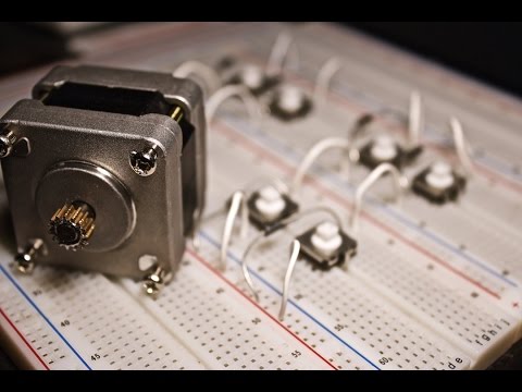
Many CD/DVD drives use a bipolar stepper motor with worm gear for linear positioning of the laser head. The tear down of an HL GCR-8483B is a good example.
Here are two similar motor units I’ve scavenged. The part numbers are un-googlable internal references:
- D4907M1F/15RF073K for upper in the picture below
- D6124NID for the lower

Drive Specifications
I haven’t been able to find any specifications for these drive units, but from my experiments I’ve gathered the following:
| Item | Specification | Notes |
|---|---|---|
| Voltage | 5V | operates from ~2.5V but at that level not able to deliver much torque |
| Current | 170mA | total current while rotating without load, including h-bridge circuit |
| Steps per Revolution | 20 | |
| Revolutions Full Travel | 11 | any attachment would reduce effective full travel |
These measurements have only been verified for the D4907M1F/15RF073K unit.
Connections
It seems the 4 wires to the drive are connected in a somewhat unusual order: A, B, D, C.
- A and B are a coil pair
- D and C are a coil pair, but reversed polarity
NB: if the connections for D and C are reversed, the stepper still “works”, but at only a fraction of the torque as half the time the coils are battling each other.

Driving a Bipolar Stepper
Some great resources for bipolar stepper motors:
- The Adafruit guide to choosing and using stepper motors
- ST Application Note AN235 “Stepper motor driving” - an excellent place to start. It’s detailed and practical.
Kevin Darrah also has a good introduction and demo of driving a bipolar stepper with push buttons:
The essence of bipolar stepper control:
- two independent coils
- exciting the coils in a specific sequence, generally either:
- in 4 full steps: 1, 3, 5, 7 in the diagram below
- or 8 half steps
- since this requires reversing the polarity on the coils, is best achieved with an H bridge

The result is 8 combinations of drive conditions as tabulated below:
- can be cycled in either direction for forward/reverse drive control
- using only the 4 steps that drive both coils (1,3,5,7) is full-step control and delivers maximum torque
- using all 8 steps provides half-step control provides more selectivity of positioning, but at a loss of torque (because half the steps only use one drive coil)
| Step | A | B | C | D | Full | Half |
|---|---|---|---|---|---|---|
| 1 | + | - | - | + | Yes | Yes |
| 2 | - | + | No | Yes | ||
| 3 | - | + | - | + | Yes | Yes |
| 4 | - | + | No | Yes | ||
| 5 | - | + | + | - | Yes | Yes |
| 6 | + | - | No | Yes | ||
| 7 | + | - | + | - | Yes | Yes |
| 8 | + | - | No | Yes |
The Arduino Stepper Library
The Stepper Library is used in the example SimpleHBridge.ino sketch.
It supports 4-wire bipolar steppers using an external H-bridge, and only implements full step control with the following sequence:
| Step | A | B | C | D |
|---|---|---|---|---|
| 1 | 1 | 0 | 1 | 0 |
| 2 | 0 | 1 | 1 | 0 |
| 3 | 0 | 1 | 0 | 1 |
| 4 | 1 | 0 | 0 | 1 |
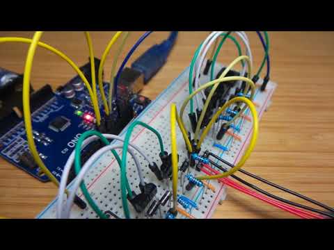
A Bespoke H-bridge Circuit
To control a bipolar stepper, we basically need an H bridge for each coil. There are dedicated chips/modules for this - a popular one being the DRV8825 Stepper Motor Driver.
But in this case I decided to build the H bridge control circuit on a breadboard. Key points to note:
- all MOSFETS not BJTs for more positive switching control
- all n-channel (rather than paired p-channel, n-channel) as control and motor circuits are running at 5V, so switching the high-side nFETs is no issue.
- I’ve included flyback diodes, though at these power levels they are not essential
I’ve included manual push-buttons in addition to Arduino control, and used these to verify drive control before hooking up the Arduino.
Construction


Performance
I hooked it up to a scope to see the control signals..

Not much to see here. However, this is a capture of the onset of one coil being activated:
