
#431 Driving the 28BYJ-48 Unipolar Stepper
All about the 28BYJ-48 unipolar stepper motor and driving it with an Arduino.

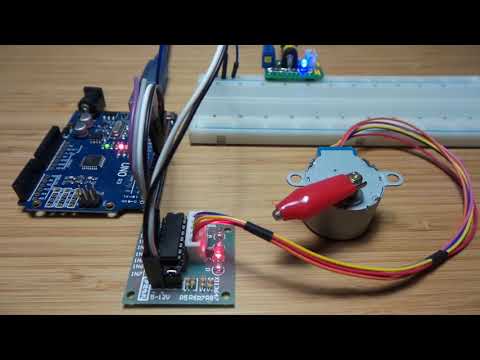
Here’s a quick demo..
Notes
The 28BYJ-48 stepper motor is pretty common in Arduino kits, and available from various suppliers on aliexpress, often supplied with an “X113647” ULN2003A driver board.
It is a 5-wire unipolar motor that runs at 5V and is suitable for cases where higher precision and torque are required, but not high rotational speed.
Driving Unipolar Stepper Motors
Unipolar stepper motors are simpler to drive than bipolar motors because no current reversal is required. This makes them very easy to control from a microprocessor platform like an Arduino, as they just require assistance to switch a higher current/voltage circuit with GPIO pins. The ULN2003A darlington transistor array is commonly used for this.
Some resources:
- The Adafruit guide to choosing and using stepper motors
- Robot Builder’s Bonanza - Working with Stepper Motors Bonus Chapters From RBB Fourth Edition
DroneBot Workshop has an excellent introduction to driving stepper motors, including the 28BYJ-48:
The essential full-step sequence:

The 28BYJ-48 Stepper Motor
The 28BYJ-48 is a 5-wire unipolar stepper motor.
| Item | Spec | Notes |
|---|---|---|
| Voltage | 5V | |
| Current | 130mA - 250mA | just based on some measurements I made while running the motor |
| Steps/revolution | 32 | |
| Gears | 64:1 reduction | because of the gearing, high speeds are not possible, but it does deliver substantial torque |
As with most motors, the power required is too much to pull directly from an Arduino, so a separate power supply is required but with a common ground.
The 28BYJ-48 or similar stepper motors are available from multiple sources, and there are two important things to note:
- wiring colors are not always consistent - I’ve seen at least two different color sequences used.
- but - almost? - always, the phase sequence is the same at the connector, but it is an order that requires re-mapping to the standard sequence used by the Stepper library (more on this later).
A good technical resources for the 28BYJ-48 is the geeetech page. Gaven MacDonald also has a good 28BYJ-48 teardown here:
The windings of the 28BYJ-48 are usually documented like this:

However, this may be a bit confusing as it doesn’t really represent how the windings energize the poles/teeth of the stator. Specifically (at least on the motor unit I have) the clockwise activation sequence is: Blue -> Pink -> Yellow -> Orange.
This translates to a full-step sequence:
| Step | Blue | Pink | Yellow | Orange |
|---|---|---|---|---|
| 1 | 1 | 1 | ||
| 2 | 1 | 1 | ||
| 3 | 1 | 1 | ||
| 4 | 1 | 1 |
Note:
- Clockwise step sequence: 1-2-3-4
- Counter-clockwise step sequence: 4-3-2-1
- Red (common) is positive
- indicates which pins are to be grounded; the ULN2003A inverts logic i.e IN1 pulled high in order to ground OUT1/Blue
A half-step sequence simply interleaves transitional steps with only one coil activated:
| Step | Blue | Pink | Yellow | Orange |
|---|---|---|---|---|
| 1 | 1 | 1 | ||
| 2 | 1 | |||
| 3 | 1 | 1 | ||
| 4 | 1 | |||
| 5 | 1 | 1 | ||
| 6 | 1 | |||
| 7 | 1 | 1 | ||
| 8 | 1 |
It is possible (although not very practical) to do a “double step” sequence with just two coils. This is useful for proving which pairs are opposing.
Clockwise:
| Step | Blue | Pink | Yellow | Orange |
|---|---|---|---|---|
| 1 | 1 | |||
| 2 | 1 |
Counter-clockwise:
| Step | Blue | Pink | Yellow | Orange |
|---|---|---|---|---|
| 1 | 1 | |||
| 2 | 1 |
The X113647 Driver Board
A driver board is usually supplied with the 28BYJ-48. There are various versions - I have one identified as X113647 - but they all essentially do the same thing:
- provide a breakout for the ULN2003A Darlington transistor array
- map four inputs (IN1-4) to the 28BYJ-48 motor connector
- link common ground between Arduino and the stepper motor
- provide the external power connector - with jumper to disable, and a decoupling capacitor
| Controller-side | Stepper-side | 28BYJ-48 |
|---|---|---|
| IN1 | OUT1 | Blue |
| IN2 | OUT2 | Pink |
| IN3 | OUT3 | Yellow |
| IN4 | OUT4 | Orange |
| - | COM: 5-12V | Red |
| GND | GND | - |

Direct Drive Example
The DirectDrive.ino sketch is an example of low-level driving the 28BYJ-48 motor via the X113647 board.
It does not use any libraries, but rather explicitly controls the 4 pins.
It runs three demo sequences in order, then repeats:
- full step, one full rotation clockwise and then back
- half-full step, one full rotation clockwise and then back
- double-full step, one full rotation clockwise and then back
Stepper Library Example
The StepperLibraryDrive.ino sketch is an example of driving the 28BYJ-48 motor/X113647 board with the standard Stepper library.
When using the standard Stepper library:
- pins must be mapped to a 1-3-2-4 sequence to work correctly
- only full-step drive is possible
To clarify the “mapping” requirement: given the sequence required by the 28BYJ-48 is:
| Step | Blue | Pink | Yellow | Orange |
|---|---|---|---|---|
| 1 | 1 | 1 | ||
| 2 | 1 | 1 | ||
| 3 | 1 | 1 | ||
| 4 | 1 | 1 |
And the Stepper Library implements the following sequence:
| Step | C0 | C1 | C2 | C3 |
|---|---|---|---|---|
| 1 | 1 | 0 | 1 | 0 |
| 2 | 0 | 1 | 1 | 0 |
| 3 | 0 | 1 | 0 | 1 |
| 4 | 1 | 0 | 0 | 1 |
Then it is readily observed that switching Pink/Yellow (C1/C2) aligns things nicely, so we end up with a pin mapping for initializing the Stepper library as follows:
Stepper myStepper(STEPS_PER_REVOLUTION, PIN_IN1_BLUE, PIN_IN3_YELLOW, PIN_IN2_PINK, PIN_IN4_ORANGE);
Construction
If you use Fritzing, it is annoying not to have parts available for these common stepper components! After searching high and low and not finding anything already available, I tried my hand at creating some custom parts (using the new part formats - most recently tested with Fritzing 0.9.0b06.11). Note that these parts are not suitable for etching your own stepper drive board, but they do work nicely enough for drawing circuits involving and X113647 or 28BYJ-48 components.
- 28BYJ-48 Stepper Motor
- X113647 Stepper Driver Board is a part for the board.
With these parts you can draw stepper motor circuits like this canonical hookup of the X113647 and 28BYJ-48 to an Arduino Uno, with external power supply for the motor. In this case, the breadboard is just a glorified cable connector.


Note the crossover of the wires emanating from the 28BYJ-48. This is actually done in the wiring of the standard connector provided with the stepper motor - but I haven’t included this detail in the part as yet.
Credits and References
- 28BYJ-48 stepper motor teardown - by Gaven MacDonald
- this geeetech page
- Arduino Stepper library
- Stepper Motor - wikipedia
- Arduino - Stepper Motor with ULN2803 IC
- ULN2003A datasheet
- Robot Builder’s Bonanza - Working with Stepper Motors Bonus Chapters From RBB Fourth Edition