
#491 Magnet-switched Solenoid
Using a Hall effect sensor to trigger a solenoid with a fixed pulse.

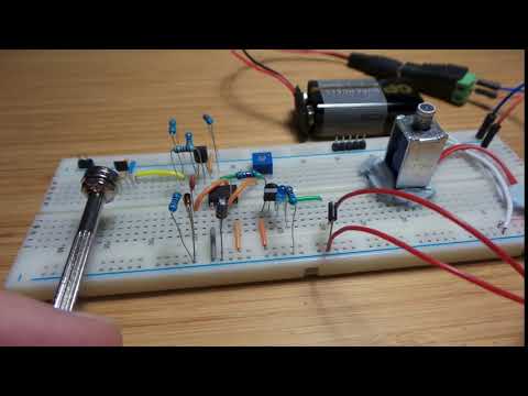
Here’s a quick demo..
Notes
The project is a demonstration of a circuit to trigger a solenoid with a hall-effect magnetic field sensor. It uses a couple of tricks to make this work:
- falling edge detection with a PNP inverter and 555 timer
- fixed duration output pulse generated by the 555 timer monostable configuration
- PNP high-side switching of the solenoid
Solenoid
For this circuit, I’m using a mini push-pull solenoid that is rated for 3-12V. The data I have from the seller page on aliexpress specifies:
- Length: 20.3 MM
- Weight: 12g
- Voltage: DC 3 V, current: 0.08 A
- voltage: 6 V, Current: 0.17 A
- voltage: 9 V, Current: 0.26 A
- Voltage: 12v, current: 0.35 A
- Internal resistance: 32.8 ohm
The switching transistor used here is the 2N3906, which is rated for 200mA continuous collector current - a little low but sufficient for this application. A 1N4007 diode provides flyback protection.
Pulse Generation
The circuit uses a 555 monostable circuit to generate a clean output pulse of fixed duration. It is triggered on the falling edge of the Hall effect sensor input i.e. when the sensor triggers (it has an open collector output).
The input edge detection is achieved with a PNP inverter being AC-coupled (via capacitor C3) to the 555 timer’s threshold input. The threshold is normally pulled low (R6), and a diode (D1) is included to absorb much of the falling edge pulse.
The duration of 555 monostable pulse is determined by R2 and C2. For testing purposes, I put a 50kΩ pot in for R2. In the final build, I settled on a fixed 4.7kΩ value, which yields an output pulse of about 52ms. Any shorter, and the solenoid does not have enough time to activate.
The output pulse from the 555 is active-low, so another PNP Q2 is used to provide high-side switching of the “load”:
- the solenoid with fly-back protection diode
- an indicator LED with current-limiting resistor
Behaviour
The scope trace below shows the pulse generated on the rising edge of the input. The output pulse is around 55ms, close to the calculated 52ms.
- CH1 (yellow) - hall-effect sensor output
- CH2 (blue) - edge-detection pulse (input to the 555)
- CH3 (red) - output, measured at the collector of the high-side PNP switch Q2

Construction

