
#416 Line Follower Kit
Building the D2-5 Intelligent Line Tracking Car Kit - a nice demonstration of a simple feedback control system with an LM393 comparator.

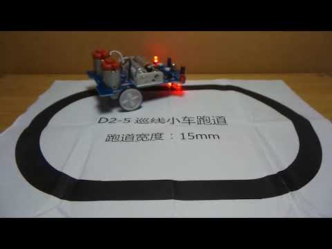
Here’s a quick demo..
Notes
The D2-5 Intelligent Line Tracking Car Kit is widely available from the usual online sources. There are a number of variations around, but they all share the same essential control circuit.
This is a neat little example of the most basic class of Line Follower Robots. It uses LEDs and light-dependent resistors on the left and right to provide feedback to control left and right motors accordingly, with an op-amp comparator providing the “brains”.
If you know someone just getting into electronics and looking for something a little more challenging than soldering an LED blinky, then I’d recommend this kit. It’s hard to get wrong, introduces a few more components, and it’s usually available cheap enough to be a nice stocking stuffer. Most importantly - it actually works!
And once it’s working - there are endless possibilities to pimp it up with custom bodywork.
Kit
Here it is - a bag of parts, PCB and instructions and a test track on a piece of A4. The instructions are in Chinese, however the PCB silkscreen has all the details marked to build the circuit correctly, and images online help get the mechanical construction right.

The PCB is single-sided, which is fine, but it does mean the LDR and LEDs on the underside of the car are actually soldered on the same side as the component. Another way to make sure you get it right: the component should always be on the same side as the silkscreen component outline.
If one is not carefully paying attention during construction, it is possible to end up with the LDR/LEDs pointing up in the air instead of towards the ground (literally: you made a bug instead of a robot).


The instructions and parts list is Chinese, and there’s a clear schematic provided:

Parts
| NO. | Component Name | PCB Marker | Parameter | Quantity |
|---|---|---|---|---|
| 1 | LM393 | IC1 | DIP-8 | 1 |
| 2 | IC Socket | IC1 | DIP-8 | 1 |
| 3 | Electrolytic Capacitor | C1,C2 | 100µF | 2 |
| 4 | Potentiometer | R1,R2 | 103, 10kΩ | 2 |
| 5 | Metal Film Resistance | R5,R6,R11,R12 | 51Ω | 4 |
| 6 | Metal Film Resistance | R7,R8 | 1kΩ | 2 |
| 7 | Metal Film Resistance | R9,R10 | 10Ω | 2 |
| 8 | Photoresistor | R13,R14 | CDS5 | 2 |
| 9 | Red LED | D1,D2 | 5mm | 2 |
| 10 | White LED | D4,D5 | 5mm | 2 |
| 11 | S8550 | Q1,Q1 | TO-92 | 2 |
| 12 | Self-Locking switch | S1 | 6*6mm | 1 |
| 13 | DC Motor | M1,M2 | 2 | |
| 14 | Wheel | 40mm | 2 | |
| 15 | Tires | 40mm | 2 | |
| 16 | Gaster nut, bolt and screw cap | M5*20mm | 1 | |
| 17 | Cable | 6cm | 4 | |
| 18 | Battery Case | AA*2 | 1 | |
| 19 | PCB D2-1 | 105721.6mm | 1 | |
| 20 | axle | 2 | ||
| 21 | axle mounts & screw | 4 | ||
| 22 | axle mounting screws | 4 | ||
| 23 | motor mounting screws | 4 | ||
| 24 | axle bushings(?) | 6 |
The D2-1 Kit
There is a variation of the kit called the D2-1. I don’t have this version, but by some reports the motors (being enclosed units) are actually easier to install and align.
See Zoomx’s postbag review for more info.

Circuit
Here is my re-drawing of the circuit - some vendors of the kit provide a schematic, others don’t.
It’s actually a nice way to learn a bit about OpAmps and using transistors to switch loads. As it’s all running at low voltage, the circuit avoids many complexities (such as dealing with flyback currents when switching inductive loads). Some key points to note:
- each motor is high-side switched, with an LED in parallel for visual feedback of “ON”
- the two comparator units in the LM393 take the same inputs but inverted, for complementary left and right control
- the comparator is wired as a simple comparison of two voltages:
- one from the left-hand LDR, the other from the right-hand LDR
- the LDRs are detecting reflected light from their partnered LED:
- white/light surfaces will reflect more energy than black/dark
- capacitors C1 and C2 provide a reserve of charge to power the LEDs, and smooth out operation as the motors place a spiky load on the battery
What happened to R3 and R4? In some versions of this circuit, these are 3.3kΩ pull-up resistors on the base of each transistor Q1, Q2. Someone obviously found out they were not really needed and saved another fraction of a cent on the BOM;-)

If you were to put this circuit on a breadboard, then like this:

Construction
The circuit was an easy solder job, with nice spacing between pads that will be fine for the less experienced.

The main tricky part of the construction is to ensure the gear wheels are correctly spaced from the board:
- too high into the gear well, and they’ll catch on the PCB and/or motor
- too low, and they may fail to mate with the worm gear nicely
The axle mounts supplied with my kit were too short as-is. There were some plastic yellow rings in the kit, and I found using one as a spacer on each axle mount provided just the right height. I thought these yellow rings were axle bushings, so I’m not sure if this was their intended use or the axle mounts were actually the wrong size. Either way - it worked out.
PS: apparently the D2-1 version of the kit avoids these issues by having fully enclosed motor/gear units.

All ready to go follow lines! It just happens that with the R1, R2 potentiometers at mid-point it worked just fine the first time in my lighting conditions and with the printed test track. YMMV, and adjustment may be necessary to keep it on track or reduce some of the “hunting” back and forth.
Credits and References
- D2-5 Intelligent Tracking Line Car DIY Kit TT Motor Electronic Assembly Smart Automobile Part Car Electronic Diy Kit
- Zoomx’s postbag D2-1 review
- Line Follower Robots - a nice introduction
- LM393 datasheet - Low Power Low Offset Voltage Dual Comparators
- Line-following Car - wikipedia
- ..as mentioned on my blog