
#526 Metal Detector Kit
An inductive metal detector kit powered by an 18650 with TP4333-based BMS charging circuit.

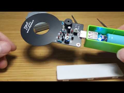
Here’s a quick demo..
Notes
I picked up a cheap Metal Detector Kit from an aliexpress seller for a few fairly prosaic reasons:
- it comes with an 18650 battery pack and I was interested in taking a look at the BMS provided
- it’s a nice black PCB;-)
- .. and maybe I can use it as a stud finder/wiring detector in the house?
The Kit
The kit comes in two parts:
- the metal detector circuit with USB connector. Working voltage: 3~5V
- 18650 battery pack and TP4333-based BMS module. Various colours are available for the batter case. It works well as a standalone 5V USB power pack.
Parts for the metal detector:
| Ref | Name | Qty |
|---|---|---|
| R1 | 200kΩ | 1 |
| R2 | 2kΩ | 1 |
| R3 | 470Ω | 1 |
| VR1 | 100Ω | 1 |
| C1,C4 | 100nF | 2 |
| C2,C3 | 2.2nF | 2 |
| C5 | 100μF | 1 |
| Q1 | S9018 NPN | 1 |
| Q2,Q3 | S9012 PNP | 2 |
| LED1 | 5mm LED | 1 |
| SW1 | Switch 6P self-locking | 1 |
| SP1 | buzzer HSD9*12 | 1 |
| USB male | 1 |


Construction
The following is my re-drawing of the core metal detector circuit. It is powered with 5V from the 18650/TP4333 battery module.


The circuit design is very similar to the Metal Detector Module available from protosupplies.
How the Detector Works
The detector comprises two inductor coils that are actually circular traces on opposite sides of the PCB.
- L1 in series with C1 (2.2nF) connects to the base of Q1 in parallel to a high-value base resistor R1 200kΩ
- L2 parallel with C2 (2.2nF) connects to the collector of Q1 and base of Q2
- L1 and L2 are wound in opposing directions
- VR1 potentiometer adjusts sensitivity by adjusting the resistance (voltage offset) at the Q1 emitter.
I think it basically works like this: When a metallic (ferrous?) object is near the coils, the inductance rises and the resonant frequencies of the L1/C1 and L2/C2 tuned circuits changes. Since L1 and L2 are in opposition, and oscillation can be sustained:
- L1/C1 turning on Q2
- Current flow through L2 will dampen L1 and throttle Q2
The TP4333 BMS
The TP4333 module comes pre-assembled and snaps cleanly into the battery case.


This is the first time I’ve seen the TP4333. It’s quite a capable little chip, combining charge control, protection and output boost converter:
- Discharge output: 5V/1A
- 1A output discharge efficiency up to 93%
- Charging current: 0.8A
- BAT discharge termination voltage: 2.85V
- Intelligent temperature control and over-temperature protection
- Integrated output over-voltage protection, short circuit protection, overload protection
- Integrated over-charge and over-discharge protection
- Supports trickle mode and zero voltage charging
The module appears to closely follow the typical application circuit from the datasheet. It doesn’t use the flashlight output though.

Low battery protection:
- when the BAT voltage is greater than 3.2V on startup, the output boost circuit is enabled.
- if the battery voltage falls bellow 3.0V during operation, LED2 will flash at a frequency of 1Hz
- when the battery voltage falls bellow 2.85V, the discharge output is disabled and the TP4333 enters low-current standby mode
Load detection and low-power standby:
- When the load is connected, it is detected by the TP4333 detect and boost circuit enabled.
- When the load is disconnected, the boost circuit is disabled after an 18s delay, and the the TP4333 enters a low-current standby mode
Credits and References
- Metal Detector Kit DC 3V-5V 60mm Detective Non-contact Sensor Module with 18650 USB Power Bank Box DIY Kit Metal Detector Finder - from an aliexpress seller
- S9018 datasheet - parts.io
- S9012 datasheet
- Metal detector - wikipedia
- TP4333 product info
- Other metal detector circuits and project ideas:
- Metal Detector Module - from protosupplies
- Metal Detector - elektormagazine
- Build Your Own Metal Detector with an Arduino - similar concept using a Colpitts oscillator
- BUILD A FOUR TRANSISTOR METAL DETECTOR - nutsvolts
- Simple BFO Metal Detector