
#274 Feeltech FY3200S
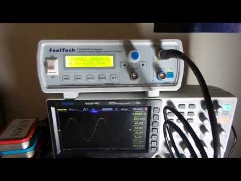
Testing out the Feeltech FY3200S digital function generator.

Notes
Because you can never have too many function generators??!
- I have one built-into my oscilloscope, but that is only really practical if you want a fixed wave or are not using the scope at the same time
- I have built my own, and will probably build more, but it is nice to have a full-featured bit of kit as a benchmark for DIY
The Feeltech FY3200S gets some good reviews and was available at a very nice price. Some of the features that I was particularly interested in:
- linear and logarithmic frequency sweep function
- dual outputs
- broad range of waveform types, and also support for user-defined waveforms
The FY3200S is available with different upper frequency limits. I have the 24MHz version, sometimes listed as the FY3224S.
Performance
In general it works great, especially the sweep function, here’s a quick demo:
Only a few comments, not necessarily that negative:
- although billed as a 24MHz generator, and while it can achieve 24MHz, I see noticeable attenuation over 20MHz
- on power-on, it always starts up with a 10V sine wave. It would be nice if it restarted with previously-used settings.
- the control layout is a bit inconvenient:
- if you use your right-hand, output coaxial cables get in the way when using the control knob
- but if you use your left-hand on the control knob, you obscure the screen
- because the push-button controls are quite stiff, and the unit is so light, you are more likely to push the unit around instead of pushing a button! Find myself using two hands - one to hold the unit in place, the other to play with the controls. The feet seem to make the problem worse rather than better. Have to find a good place in the workspace desk where it won’t go skirting around..
Inside
The FY3200S comes in a nice instrument case, and inside is … well, a lot of air really;-)

The unit essentially comprises three modules
- a switch-mode power supply
- USB/serial adapter
- mainboard and front-panel controller


The Floating Ground Problem?
The unit does not have high-power requirements, but I presume it needs pretty clean power. A simple switch-mode power supply does the job:

It is important to note that output connections are not earthed, but are instead floating by design. Due to the suppression capacitor across input and output, this can mean the output ground floats significantly above earth ground. A quick check of the “ground” on my FY3200S shows me it is running about +80V above earth.
This has been highlighted in a number of reviews such as SDGMB #006 FeelTech FY3224S 24MHz Signal Generator Banggood by SDG Electronics.
Connecting the output ground to earth ground works fine, with any ground leakage below what I was able to measure (<10µA).
As some have pointed out, floating grounds may not be desirable in test equipment. If desired, it is a relatively simple modification to permanently earth-ground the connectors (also entails changing the power socket and cord).
But either way - floating or earthed - it is always advisable to stop and think ground and power levels before interconnecting equipment.
Product Specifications
From the seller’s site…
Features
- Using DDS direct digital synthesis technology to generate precise, stable, low distortion output signal.
- CH1 and CH2 completely symmetrical two channels, each channel can be independently set the parameters.
- Supports user-defined waveform, each arbitrary waveform memory depth 2048 * 12bits, 250MSa/s sampling rate.
- With pulse trains burst output function, manual trigger, internal CH2 trigger and external trigger three trigger modes that allow the unit to any output 1~1048575 arbitrary pulse trains.
- Measurement functions: 100MHz frequency meter and counter function.
- Signal output amplitude range is 10mVpp- 20Vpp, DC offset adjustment range is -10V to 10V, the resolution is 0.1V.
- Digital signal output function, CMOS output range 0~10V.
- Waveform generator up to 12 bits wide, the output waveform is more delicate, waveform distortion is low.
- With full CNC functions, display and adjust of current output signal parameters, such as the amplitude, offset, frequency, duty cycle, and the phase difference of two signals.
- After connected with computer, user can control signal generator functions and parameters, and can edit and download arbitrary waveform.
- High frequency accuracy and resolution: frequency accuracy up to 10^(-6) magnitude, total range frequency resolution is 10mHz.
- Tracking function: built-in frequency, amplitude, offset, duty cycle, waveform and other parameters follow function, easy to use.
- Scanning features: frequency linear sweep and logarithmic sweep function, start and end points of scanning can be set freely.
- Storage features: can store 20 groups parameters set by the user.
- Operation: key operation, LCD1602 display in English, directly digital setting parameters or continuous adjustment knob.
- Input over-voltage protection: extended power input range is AC85V to AC260V wide voltage.
- Output short-circuit protection: all signal output can work above 60s in load short-circuit situation.
Frequency Parameters
| Item | Specification |
|---|---|
| Frequency Range | 0Hz~24MHz |
| The Min. Frequency Resolution | 10mHz (0.01Hz) |
| Frequency Accuracy | ±5*10^(-6) |
| Frequency Stability | ±2*10^(-6)/3 Hours |
| Phase Adjustment Range | 0~359° |
| Phase Resolution | 1° |
Waveform Types
| Item | Specification |
|---|---|
| Output Waveform Types | Sine, Triangle, Square, Sawtooth, Pre-defined, User-defined |
| Pre-defined Waveforms | Pulse Wave, Lorentz Pulse, Multi-tone, Random Noise, Electrocardiogram, Trapezoidal Pulse, Symplectic Pulse, Narrow Pulse, Gaussian White Noise, Amplitude Modulated, Frequency Modulated |
Waveform Parameters
| Item | Specification |
|---|---|
| Sine Wave Harmonic Distortion | ≤0.8%(Referent Frequency 1KHz) |
| Square Wave: Rise/Fall Time | ≤20ns(Referent Frequency 100KHz, 10Vpp) |
| Square Wave: Overshoot | ≤7.5% |
| Square Wave: Duty Cycle | 0.1%~99.9% |
| Sawtooth Wave Linearity | ≥98% (0.01Hz~10KHz) |
| Pulse Wave: Pulse Width Adjusting Range | 10nS~1S |
| Pulse Wave: Rise/Fall Time | ≤20ns |
| TTL Output: Level Amplitude | >3Vpp |
| TTL Output: Fan-out | >20 TTL Load |
| TTL Output: Rise/Fall Time | ≤20ns |
| CMOS Output: Low Level | <0.3V |
| CMOS Output: High Level | 1V~10V |
| CMOS Output: Level Rise/Down Time | ≤20ns |
Waveform Output
| Item | Specification |
|---|---|
| Output Impedance | 50Ω(±10%) (Typical) |
| Output Amplitude | ≥20Vpp(No Load) |
| Protection | All signals output can work above 60s under the condition of load short circuit |
| DC Offset Adjustment Range | ±10V |
| Offset Resolution | 0.1V |
External Measurements
| Item | Specification |
|---|---|
| Frequency Measuring Range | GATE-TIME=1S 1Hz - 100MHz |
| Input Voltage Range | 1Vpp~20Vpp |
| Counting Range | 0~4294967295 |
| Periodic Measurement | 20ns Resolution, the Max. Measurable 20s |
Scanning Function
| Item | Specification |
|---|---|
| Scan Mode | Linear Sweep, Logarithm Sweep |
| Scan Object | Frequency |
| Scan Time | 1s-999s/Step |
| Frequency Setting Range | Start Point and End Point can be set arbitrarily |
| Frequency Scan Range | It is determined by the sweep parameter settings |
General Parameters
| Item | Specification |
|---|---|
| Memory: Quantity | 20 |
| Memory: Location | M0 to M19 (01 for default value) |
| Interface: Interface Mode | Using USB to Serial Interface |
| Interface: Communication Speed | 9600bps |
| Interface: Protocol | Command Line Mode, Protocol Complete Open |
| Power Supply Voltage Range | AC 85V to AC 260V |
| Display Display Type | LCD 1602 Display |
| Environment | Temperature: 0~40°C Humidity: <80% |
| Size | 19 18 7cm / 7.5 7 2.75in (L W H) |
| Weight | 577g / 20.36oz |
| Package Size | 25 21 9.5cm / 9.84 8.27 3.74in (L W H) |
| Package Weight | 913g / 32.23oz |
Package List
| Qty | Item |
|---|---|
| 1 | Function Signal Generator |
| 1 | USB Cable |
| 1 | Power Plug |
| 1 | CD |
| 2 | BNC Clips Cable |
The CD contains soft copy of the manual.
It also includes software for user-defined function generation/loading. I haven’t tried any of the software yet as it is all for Windows only.
There is, however, a copy of the FY3200S Series Communication Protocol Specification. It defines a quite simple serial protocol that runs at 9600bps, so it appears that it would be a relatively straight-forward task to write one’s own software to control the device.
Credits and References
- Digital DDS Function Signal Source Generator Arbitrary Waveform/Pulse Frequency Meter Dual-channel12Bit 250MSa/s Sine Wave 24MHz - from an aliexpress seller
- feeltech.net
- FY32xxS Series User’s Manual V1.4
- Re: FeelTech FY3224S 24MHz 2-Channel DDS AW Function Signal Generator
- FeelTech Signal Generator FY3200S, FY3224S - good feature review
- Feeltech FY-3200S - Frequency counter function - review on youtube
- SDGMB #006 FeelTech FY3224S 24MHz Signal Generator Banggood - review on youtube