
#407 DPS3005 Bench Power Supply
Building an AC-powered 32V/5A variable bench power supply based on the DPS3005 DC power supply module and rectified step-down transformer.

Notes
The DPS3005 is one of a range of popular DC power supply modules; this one is designed for up to 32V/5A DC output.
For this project, I am mounting the DPS3005 in a project case, and adding mains AC power supply.
DPS3005
I obtained a DPS3005 module from a seller on aliexpress - this appears to be the official store for the producers, RD Tech.
Technical parameters
- Input voltage range: 6.00-40.00V
- Output voltage range: 0V-32.00V
- Output current: 0-5.000A
- Output power range: 0-160.0W
- Product Weight: about 113g
- Product Dimension: 794348(mm) (LWH)
- Open size: 71mm*39mm
- Output voltage resolution: 0.01V
- Output current resolution: 0.001A
- Output Voltage accuracy: ± (0.5% + 1 digits)
- Output Current accuracy: ± (0.5% + 2 digit)
Power Supply
The DPS3005 requires a maximum 40V DC input power supply. I’m providing this with an AC step-down transformer and bridge rectifier and smoothing capacitor. I have not added noise protection or filtering, as I’m expecting the DPS3005 module to take care of this itself.
Components I’ve selected for the power supply:
- Fused 3-terminal Power Socket with illuminated switch
- 220V to 18V RMS, 15W step-down transformer
- KBU2510 25A/1000V diode bridge rectifier
- 82µF/450V electrolytic capacitor
With the 18V transformer, the rectified DC voltage is around 30V, limiting the maximum voltage I’d get out of the unit to about 25V (which is fine for me).
The basic idea in schematic form:

Fused and Illuminated Power Switch
I have some panel-mounting power sockets that I’ll use for the project - OOTDTY AC 250V 10A 3 Terminal Power Socket with Fuse Holder on aliexpress. Key features:
- takes a 3-pin power cord (similar to those used for PCs)
- rated for 350V at 10A
- integrated fuse holder
- illuminated power switch
The nice thing: just one square hole to cut in the panel!
I had to research and test for the correct connections to the power switch in order to have it illuminate correctly. The best explanation I found of how it works is in this video:
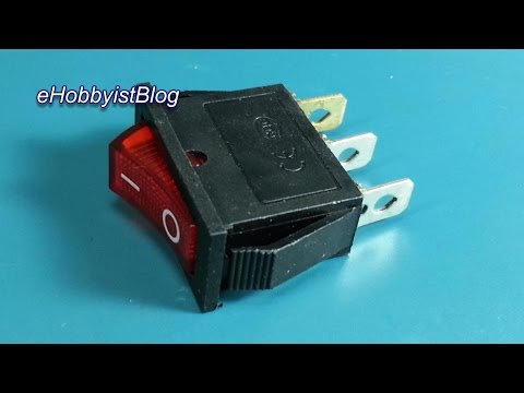
I still had to get the correct pins for this particular switch (marked: XL601-101A and rated for 6A at 250V):
- 1: Live to circuit
- 2: Live in
- 3: Neutral in (copper pin)
The switch schematic appears like this:

When installed and powered on:

Bridge Rectifier
I could have built a rectifier with discrete diodes, but I don’t have any on hand that are rated for the theoretical limits of the DPS3005. Instead, I decided to use a KBU2510 rectifier package. It is well over-specified at 25A/1000V.
For smoothing, I have a single 82µF/450V electrolytic capacitor
Grounding
I’ve decided to keep the DC output supply floating i.e. not referenced to earth ground: the secondary of the transformer, rectifier and DPS3005 have no earth connection.
If earth grounding is required, this would just need to be done in the circuit under power.
The metal panels in case are connected to earth ground (from the power plug), shunting any short circuit and presumably blowing the fuse in the power socket or tripping a circuit breaker on the mains circuit
Enclosure
I’ve mounted the project in a 6.7” x 5.1” x 3.1” Blue Metal Enclosure Project Case DIY Junction Box, and use a dual banana binding post for the DC output terminals.


Usage
The controls are quite easy one you get used to them (NB: scan of the english manual here)
- Direct constant voltage or constant current control
- output on/off
- Base settings for over-voltage, over-current, over-power (unit will turn off the output if any of these limits are exceeded)
The colour LCD provides all the information including instantaneous output voltage, current and power.
Test & Performance
Under test with 5V out: interestingly, the actual output voltage as measured with a DMM matches the constant voltage setting, but the on-screen output voltage is off by ~10mV.
As noted by @alex1sh here, there is quite a bit of noise on the power supply output.
Here’s an AC-coupled scope trace of the output (set to 3.3V) with no load. This pretty much corresponds with background noise I have in my work area:

The following trace is with the signal cleaned up with an L=47µH and C=100nF filter on the output. NB: those values are not calculated, just an experimental guess.

[@alex1sh notes:]https://github.com/tardate/LittleArduinoProjects/issues/12#issuecomment-456918689)
From time to time, I am using this PSU for high current application, i.e. 3-5A. Therefore, I decided to go for this inductor: https://www.digikey.co.uk/product-detail/en/murata-power-solutions-inc/1410454C/811-1345-ND/1924845 It is 100µH and 5.4A rated. With regards to the capacitor, I have not figured out the most appropriate value yet. Right now I have 470µF one.
Conclusion: where clean power is required, this unit needs external filtering.
Credits and References
- RD DPS3005 Constant Voltage current Step-down Programmable Power Supply module buck Voltage converter color LCD voltmeter
- OOTDTY 1Pc New Black Red AC 250V 10A 3 Terminal Power Socket with Fuse Holder
- 6.7” x 5.1” x 3.1” Blue Metal Enclosure Project Case DIY Junction Box
- Dual Banana Plugs Binding Post
- RDTech DPS series - wiki
- KBU2510 datasheet
- ..as mentioned on my blog