
#568 Beep Logic Probe
Building a logic probe with audio and LED feedback, based on a design from Elektor magazine January/February 2015.

Here’s a quick demo..
Notes
The “Beep Logic Probe” appeared in Elektor magazine January/February 2015 and is a nice little circuit for probing digital circuits. Main features:
- “high” and “low” states generate a beep with high and low frequencies respectively
- high Z/disconnected state is silent
- a separate frequency counter triggers an audio tone for high frequency signals (I’ve used it to detected signals all the way up to 24MHz)
- powered from the circuit under test with a wide voltage range (3-15V) since it uses 4000-series CMOS devices
I’ve made a few modifications to the original Elektor circuit:
- the front-end is replaced by dual comparators using an LM358, so that the high-Z range is explicitly set between 1/3 and 2/3 of VCC
- the three-stage voltage divider front-end in the original circuit did not work very well for me, as it would not unlatch low signals effectively -the transition voltages of the CD4040 NAND gate I’m using appeared to be on the high end of the specs, and thus defeated the “high Z” state of the circuit
- although this circuit is primarily audio, I’ve added LED indicators just for fun:
- red - low voltage indicator
- green - high voltage indicator
- orange - high frequency detection indicator
- the original circuit tapped 3 selectable outputs from the CD4093 ripple counter. I’ve only tapped two, and used a third for the LED indicator.
- I’m using CD4049 inverting buffer instead of the original CD4050 non-inverting buffer. As this is used just for driving the audio output, the result is the same.
How it Works
See the Elektor article for a full description. The essentials:
- low and high frequency audio indicators are generated with simple NAND-gate oscillators. This allows the neat trick of using the input signal as an enable input to the oscillators
- higher frequency signals will soon drive the circuit beyond audible range. This is where the CD4093 ripple counter comes into play - it is capacitively coupled to the input and scales back the incoming signal. The frequency range switch is used to select between divide by 1024 or 2048.
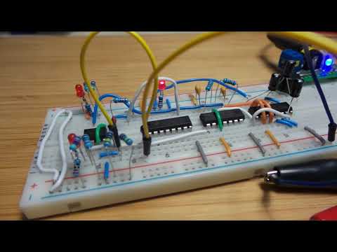
Construction
First with a breadboard test:


A quick test with a function generator on the breadboard:
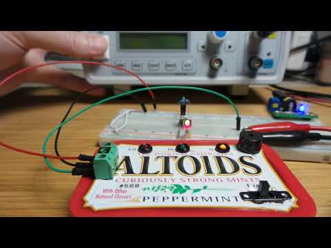
Altoids Can Construction
I transferred the circuit to a piece of protoboard using the following layout and then stuck it in an Altoids can..


A Quick Test
In the following demo, I’m probing a simple 555 astable oscillator, and then monitoring the output of a function generator all the way up to 24MHz
Credits and References
- Beep: Logic Probe/Tester - as appeared in Elektor magazine January/February 2015
- Elektor PCB
- CD4040 datasheet
- CD4049 datasheet
- CD4093 datasheet
- LM358N Datasheet