
#205 TriacDimmer
Investigate the operation of triacs and build the basic dimmer circuit.
Notes
A triac is a “bidirectional thyristor” because it conducts in both directions and is typically used in AC applications.
For standard triacs, current flow in either direction between the main terminals MT1(A1) and MT2(A2) is triggered by a small signal current applied between MT1(A1) and the gate terminal.
The basic behaviour of a triac can be summarised in two rules:
Rule 1. To turn ON, a gate current ≥ IGT must be applied until the load current is ≥ IL (latching current).
Rule 2. To turn OFF (commutate), the load current must be < IH (holding current) for long enough for the device to return to the blocking state.
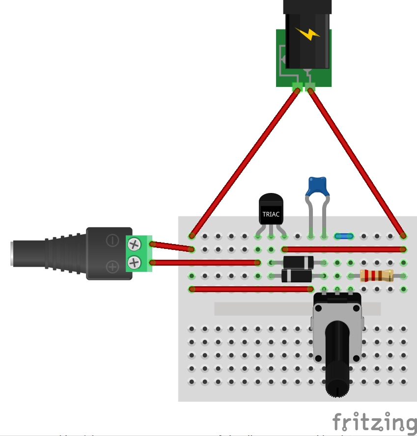
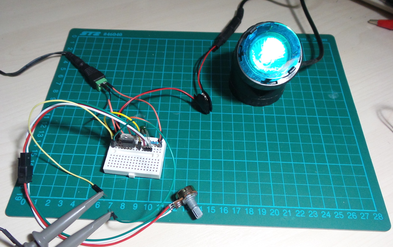
Dimmer Circuit
The AC dimmer is a classic application of Triacs. It allows power to be dialed down by effectively chopping out part of each cycle.
Here I’m using a 12V AC supply and a 12V AC lamp and a BTA12-600B Triac.
The gate is controlled by a R-C network. A variable resistor is the dimmer control.
Triacs are often paired with Diacs on the gate to enhance stability. It is not required for a simple dimmer. But here I’ve included two anti-parallel diodes to simulate the function of a diac.
Behaviour
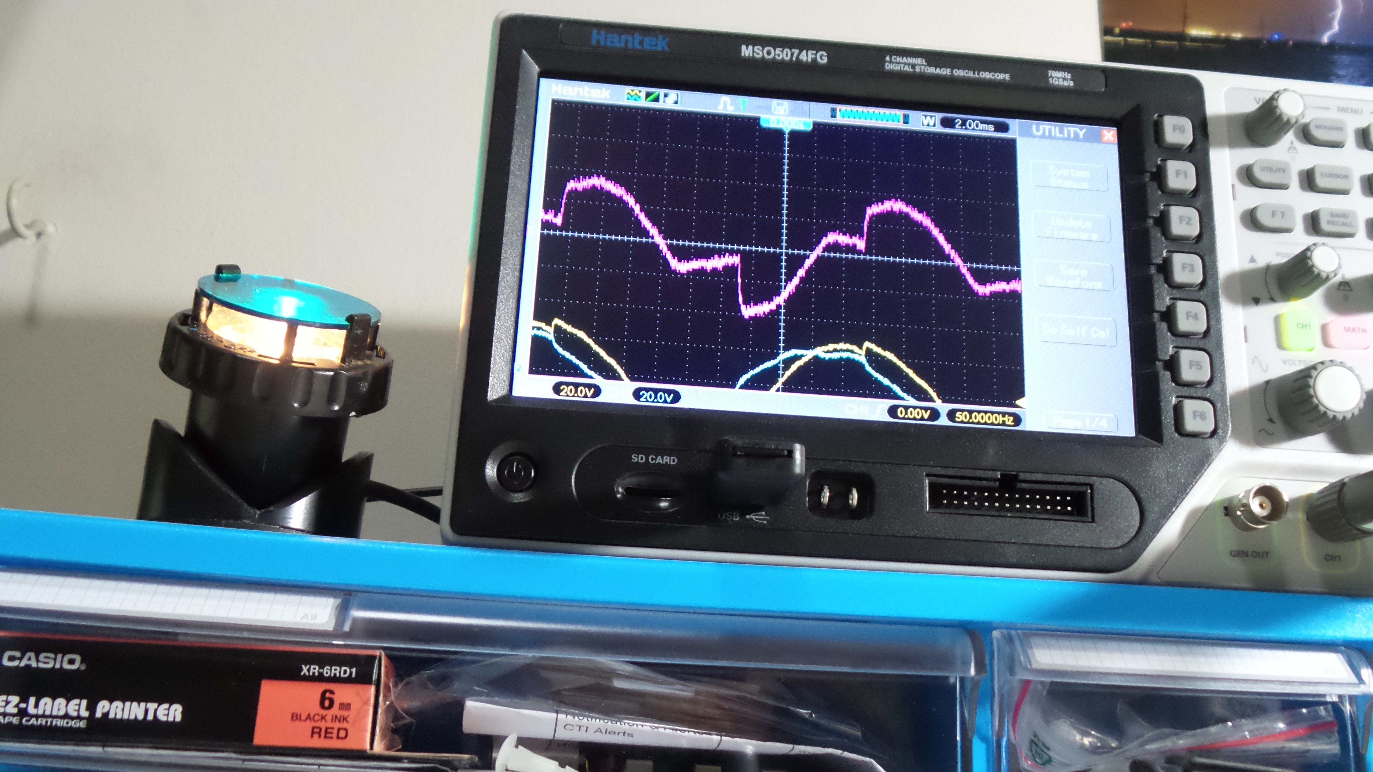
With the dimmer “half on”, the characteristic Triac cut out on both sides of the cycle is pretty clear to see. I was expecting a cleaning signal than this. Is this normal? Not sure, perhaps I should solder up the circuit and try again on something more stable than a breadboard.
With the dimmer right down (but light still on - just), the wave eventually breaks down. One half of the cycle drops before the other, as can be seen here:
NB: since I don’t have a differential probe, these scope traces are the X+Y mix of two channels measuring both connections of the lamp with respect to ground.
Construction

Credits and References
- Triacs - wikipedia
- Thyristors & Triacs - Ten Golden Rules for Success In Your Application - great document, pretty much all you need to know!
- BTA12-600 Datasheet
- Triac Tutorial and Basic Principles
- Basic Triacs and SCR Projects and Circuits
- What is a TRIAC - Tutorial
- Dimmer Theory
-
[Electronic Basics #20: Thyristor, Triac Phase Angle Control](https://www.youtube.com/watch?v=4N1uLth1o9o) - ..as mentioned on my blog