
#172 SCR Latch
Exploring the behaviour of low-power silicon controlled rectifiers (SCR)
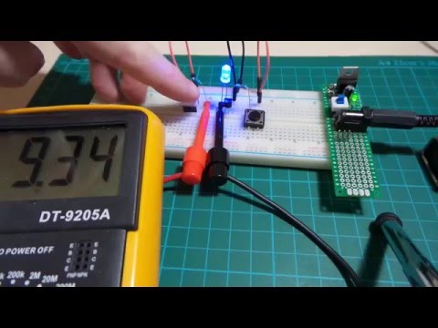
Here’s a quick video of the test circuit in action:
Notes
Silicon controlled rectifiers (SCR) are unidirectional devices, with the anode-cathode path controlled by a gate. SCRs are sometimes referred to as thyristors, although “thyristor” can also mean the whole class of 4+ layer devices including triacs and silicon controlled switches (SCS).
The fundamental behaviour of an SCR boils down to two facts:
- they turn on when a gate current ≥ I(gt) is applied until the load current is ≥ latching current I(l)
- they remain on as long as the load current is ≥ holding current I(h) - even in the absence of gate current

There are other ways to turn on an SCR, such as forward-voltage avalanche breakdown. See the wikipedia page for more details.
DC Applications
With DC loads, the SCR is an idiosyncratic device - like a switch you can turn on but can’t turn off! At least not without separately switching the load current.
Applications can include alarms, since contact switches could activate the alarm but require a separate reset switch to turn off.
AC Applications
With AC, every cycle falls below the holding current, so SCRs become more useful as on/off switches often in low power situations. But since they are unidirectional - therefore act like half-wave rectifiers - it’s perhaps more likely to see bidirectional Triacs in use.
DC Test Circuit
Here I’m testing a BT169D “logic level” SCR that can handle modest loads up to 0.8A RMS and be controlled by low-power gate trigger circuits.
Critical facts from the datasheet:
| Parameter | Typical Value | Max Value |
|---|---|---|
| I(gt) | 50µA | 200µA |
| V(gt) | 0.5V | 0.8V |
| I(l) | 2mA | 6mA |
| I(h) | 2mA | 5mA |
These are very “nice” values for digital logic and microcontroller circuits!
I’m going to build this circuit on 5V power, and use an LED as a representative load. Two things to consider:
1. Designing for sufficient gate current
For triggering, assuming typical V(gt) I should be able to get 200µA gate current with a 22.5kΩ series resistor.
I’ll use 10kΩ to allow a generous margin and ensure the gate turns on (still nowhere near the gate current maximum of 1A). Theoretically this should give me a nice 450µA gate current.
In practice, I’m seeing 436µA I(gt) - perfect; the difference is explained by V(gt) actually being around 0.7V under this load.
The 1MΩ pull-down resistor R3 is not required for the gate to operate - it’s only included to ensure a clean signal for the scope, rather than let the gate float.
2. Designing for sufficient load current
For my LED load, I’m using a blue LED with a forward voltage (Vf) of around 3.1V.
Once latched I want the LED to remain on so the load current needs to be greater than the minimum latching current (6mA) but less then the LED’s limit (20mA). Let’s say 10mA.
The BT169D datasheet has a “Typical and maximum on-state characteristic” graph which shows that V(t) i.e. the anode-cathode voltage drop can is typically in the region of 0.8V with such a low current.
So it looks like a 100Ω current-limiting resistor will do the job.
In practice, I measure 9.45mA load current - perfect; the difference is explained by V(t) actually being closer to 1V.
Trigger Trace
Here’s a trace of the trigger event. I purposely chose a bouncy capture to illustrate the fact that once latched, the SCR remains on.
- CH1 measures the voltage across the gate and resistor - the trigger signal.
- CH2 measures the voltage at the SCR anode - this drops to ~ 0.8V when the SCR turns on

Construction
Notes:
- I created a custom Fritzing Part available here for these diagrams.
- the 1MΩ pull-down resistor R3 is not required for the gate to operate - it’s only included to ensure a clean signal for the scope, rather than let the gate float.


Credits and References
- Silicon controlled rectifier - wikipedia
- BT169D datasheet
- Thyristors & Triacs - Ten Golden Rules for Success In Your Application - great document, pretty much all you need to know!