
#472 Capacitive Dropper Power Supply
Understanding how to design a capacitive dropper, demonstrated with a low-voltage LED driver circuit.
Notes
Capacitive power supplies aka capacitive droppers, are cheap and simple designs for generating a current-limited, rectified voltage, usually from mains power.
See LEAP#067 for an example of this used for mains powered LED lamp.
The essence of a capacitive dropper is to use a mains-rated capacitor in series with the power line. The capacitive reactance at the supply frequency will limit the current that can be drawn.
Give a capacitive reactance Xc = 1/ωC = 1/2πfC, the available current is I = Vac/Xc.
There are particular safety concerns with capacitive droppers:
- the rectified circuit is not isolated, and will float relative to mains power.
- capacitors may retain a mains charge after power is disconnected if bleeder resistors are not included in the design
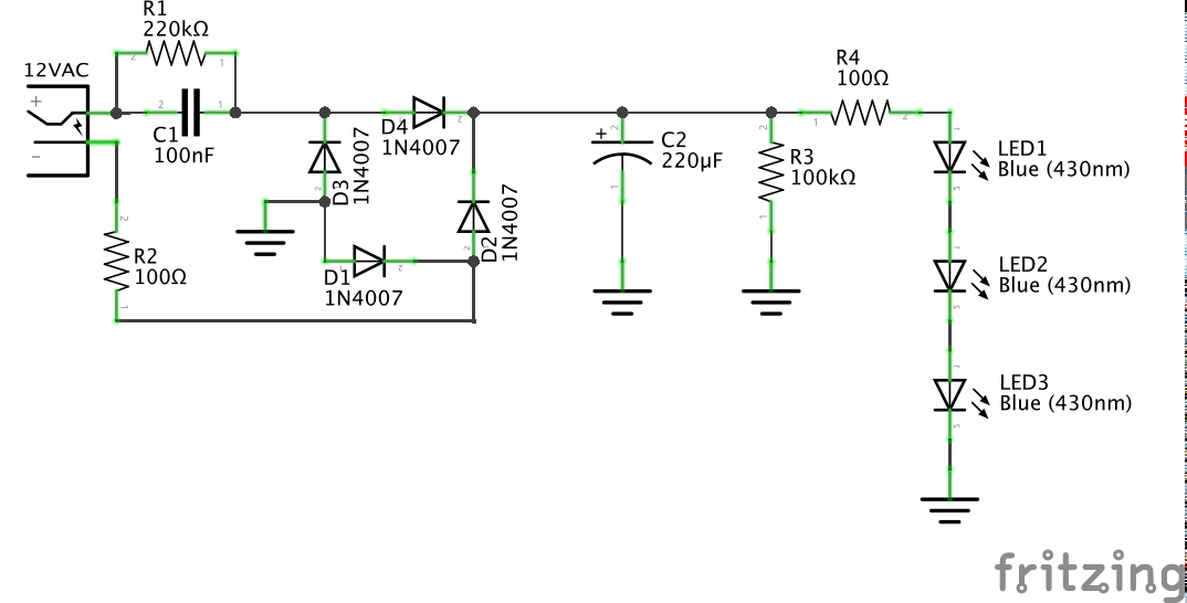
Typical capacitive droppers include the following circuit stages:
- AC power input with live and neutral connections. Most dropper circuits are not earthed or isolated.
- Capacitive current limiter C1 with parallel residual voltage protection R1
- Series resistor R2 to limit the impact of power-on voltage spikes on C1
- Full-wave rectifier
- DC bypass/smoothing capacitor C2
- C2 residual voltage protection R3.
- Finally, the load - often just LEDs in series with a small resistor R4 to take up the slack in the voltage drop.
Voltage regulation may be added to the load circuit if it is important.
Low-power Demonstration Circuit
A good way of experimenting with dropper circuits is to avoid the high voltage risks of mains supply and use a low voltage AC adapter. In this example, I’m using a 12V AC power adapter rated for 10VA.
I am using a 0.1µF X2 capacitor for C1. In my location, our mains power is 50Hz, so the capacitive reactance Xc = 1/ωC = 31.8kΩ, and at 12VAC, the circuit should be limited to around 0.38mA. That’s quite low, but ample for the LEDs I am driving.
I’ve set R1 at 220kΩ, so the discharge time constant on power off is 22ms. This is perhaps on the low side for 50Hz, and would be better sized at say 1MΩ for a 100ms time constant.
C2 is quite a chunky DC bypass capacitor of 220µF. This does provide very smooth power, but of course also means a slow ramp of the voltage at startup and shutdown. With R3 at 100kΩ, the discharge time constant on power off is also very slow at 22s. A better choice for C2 may be say 4.7µF, for a discharge time constant of 0.47s.
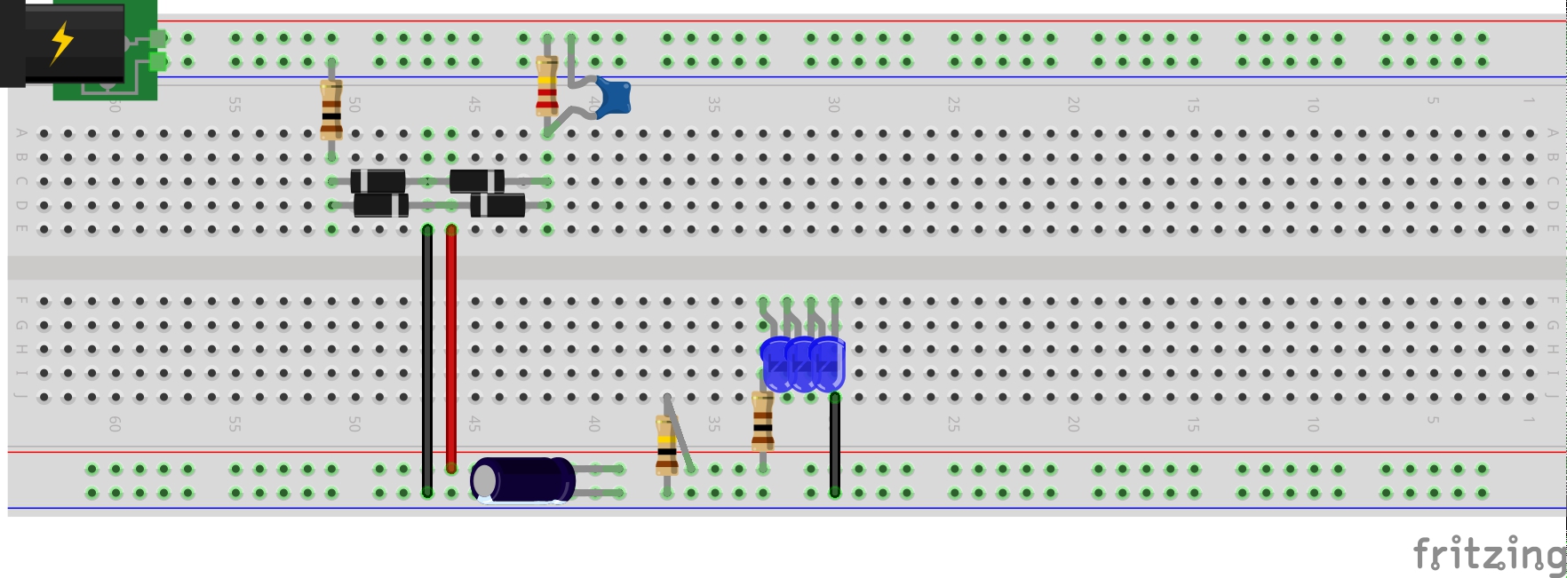
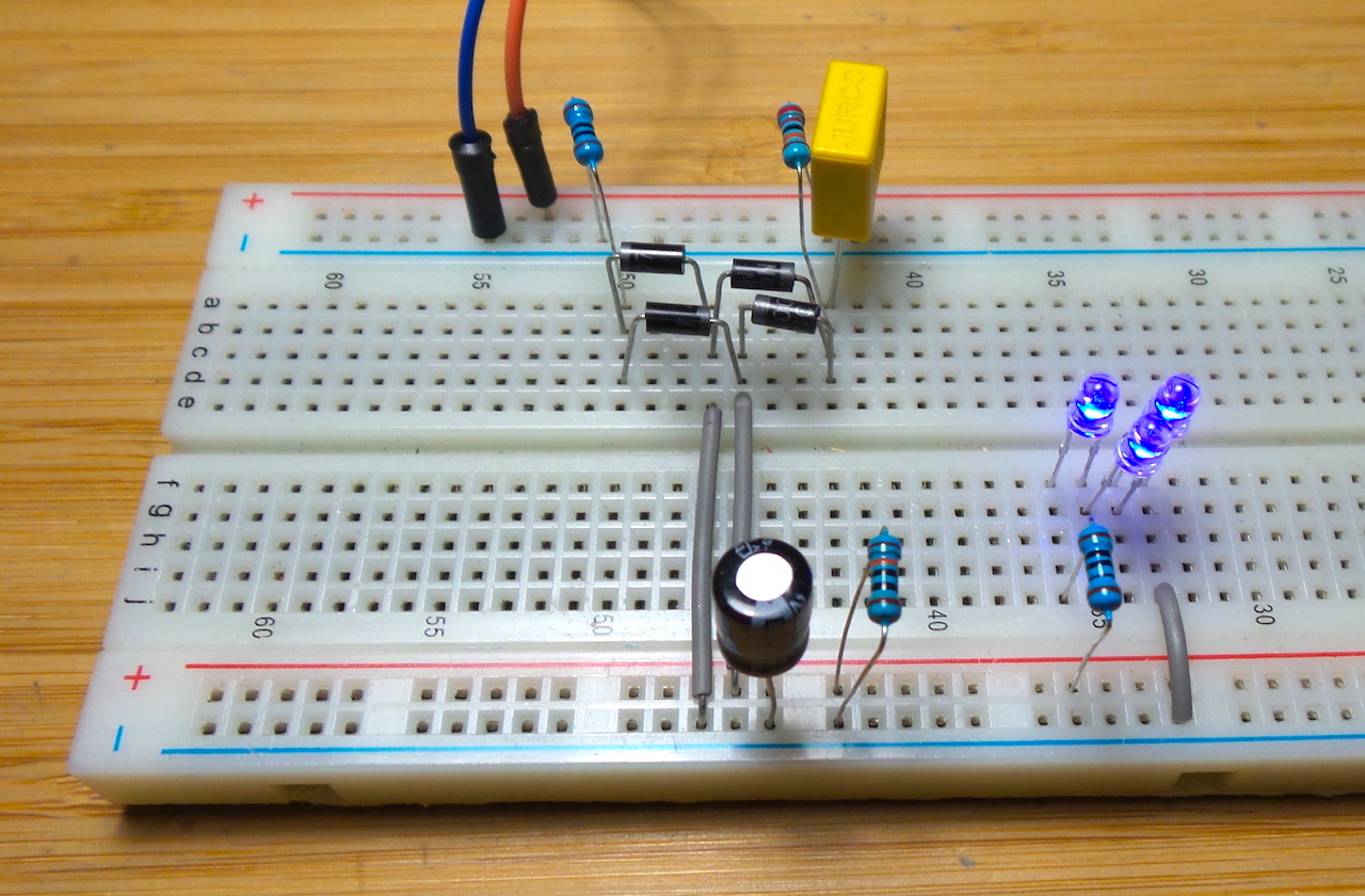
Initial testing on a breadboard:
Here’s a scope trace of:
- CH1 (Yellow) - AC input
- CH2 (Blue) - AC voltage across the bridge rectifier and R2 i.e. after C1
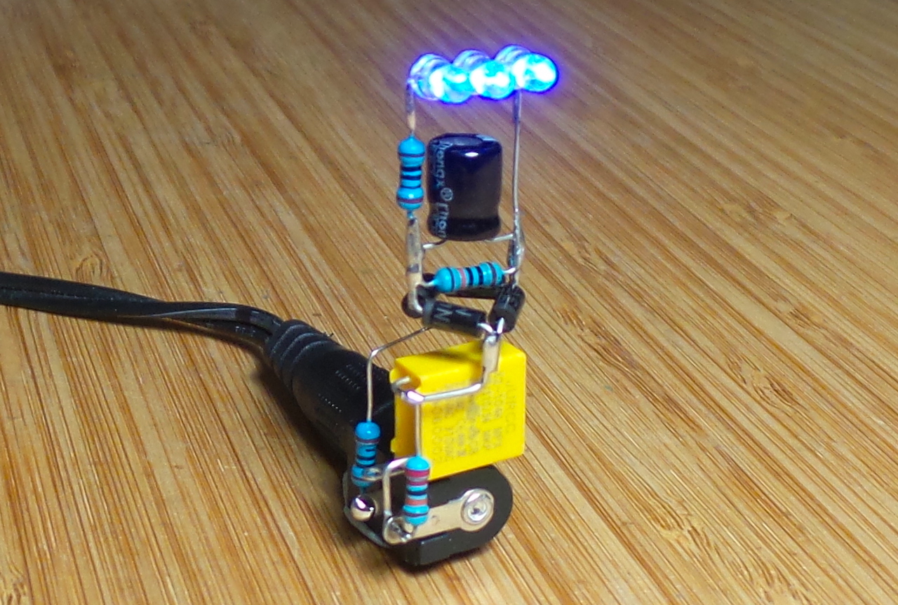
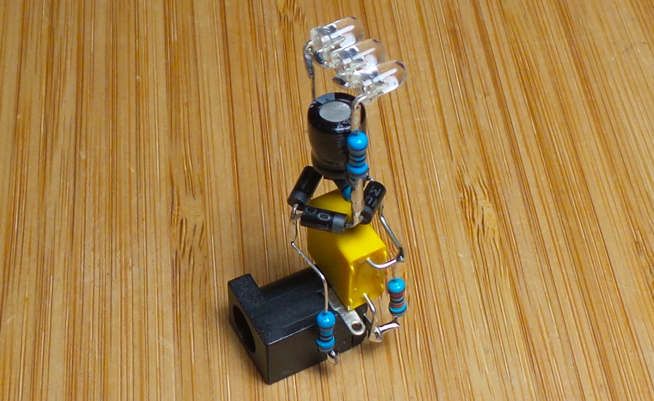
Freeform Build
Just for fun, I whipped up a freeform realisation of the circuit.
Credits and References
- capacitive power supply - wikipedia
- Some good capacitive dropper circuit/project write-ups:
- one of a few questions on EE.SE on the subject.