
#511 Bridge Doubler Split Supply
An AC-powered bridge doubler supply with DC output governed by 7815/7915 ±15V DC linear regulation.

Notes
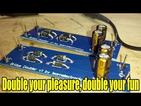
Learnelectronics recently had a good video on Youtube covering the Delon/full-wave bridge doubler circuit, which prompted me to take a closer look at this classic circuit.
I’ve taken some measurements of the basic circuit powered by a 12VAC adapter, and then added ±15V linear (7815/7915) regulation for a handle split-supply unit that could be quite handy on the bench.
The Basic Bridge Doubler
The “Delon” voltage doubler topology comprises two half-wave peak detectors, so the DC output is twice the peak input voltage. This can be used as a single-sided DC supply, or by using the centre tap, as ± split supply.
In my build, I’m using an isolated 12AVC power adapter. If mains supply is used for the circuit, tapping the centre connector can be very unsafe unless care is taken to ensure this is wired to the neutral mains wire.
Any sufficiently-rated rectifier would do for the bridge, however I’m using 1N5819 for low forward voltage to minimise loss. For testing, a 10kΩ resistor is in-circuit as a representative load.


With a couple of LED voltage meters attached, we can see about ±19.5V on the output:

The scope trace below shows the capacitors doing their job as peak detectors, sagging a bit due to the load. In the trace:
- CH1 (yellow) - AC input
- CH2 (blue) - positive DC output
- CH3 (red) - negative DC output

Adding ±15V Regulation
With ±19.5V, that’s just enough headroom for a ±15V regulated supply, so I added regulation with 7815/7915 positive and negative regulators in a standard configuration. I bumped up the output capacitors to 2.2µF to eliminate noise I was seeing on the negative rail.
Since Fritzing lacks good 7815/7915 parts, I redrew the schematic in EasyEDA:
I’m using a couple of nice little 24V Edison indicator lamps on the output as a test load.


The scope trace below shows the capacitors doing their job as peak detectors, sagging a bit due to the load. It’s apparent this is operating pretty much at the load limit before regulation would start to break down. In the trace:
- CH1 (yellow) - AC input
- CH2 (blue) - negative DC output before regulation
- CH3 (red) - negative regulated DC output
- CH4 (green) - positive regulated DC output

Transferred to protoboard with the following layout. I’ve included some gratuitous LEDs on each side of the supply - a pair of 5mm strawhat LEDs with 4.7kΩ current-limiting resistors. Green for the +15V rail, red for the -15V rail:

Under test with some 24V edison lamps:

Credits and References
- Voltage doubler - wikipedia
- Voltage Multiplier - electronics-tutorials
- 7815 datasheet +15V regulator
- 7915 datasheet -15V regulator
- 1N4001 datasheet 50V standard recovery rectifier
- 1N5819 datasheet - Schottky Barrier Diode
- Edison indicator lamps 24V - aliexpress