
#439 QX5252 Solar Night Light
Exploring the circuit inside most garden solar lights, which uses a QX5252/YX805 boost and charge controller.

Here’s a quick demo..
Notes
Inside most solar-powered garden lights is an ingenious little circuit comprising a rechargeable battery, solar cell, inductor, LED and a little IC that does all the magic:
- when voltage is detected from the solar cell, the LED is off and the battery will charge
- as the solar cell voltage drops off (gets dark), the chip runs a switching converter (using the inductor) to boost the voltage from the 1.x V battery sufficient to drive the LED
- when the battery voltage falls too low, it tuens off the boost converter to prevent over-discharge
The chips that do the work are typically 4-pin TO-94 packages and come from various sources. Some of the most common are the QX5252 and YX805. I’m using a QX5252 here as it is the one I found a reasonable datasheet for.
There are DIP versions of these chips that have an additional light control pin that can either be used as a simple on-off, or to adjust the PVC voltage at which the LED cuts-off. I’m not using this as I have the TO-94 package version.
This project is a simple demonstration build of the standard solar-powered LED circuit.
Rechargeable Battery
I’m using an Energizer HR03 with a nominal voltage of 1.2V. I bought a pack of 2 with a charger (which I hopefully don’t need!):

Inductor Selection
The inductance will determine the current available to drive the LED load.
According to the QX5252 datasheet, indicative values are as follows for a nominal voltage of 1.3V:
| Inductance | Current |
|---|---|
| 330µH | 11mA |
| 270µH | 14.5mA |
| 220µH | 15.5mA |
| 150µH | 25mA |
| 100µH | 34.5mA |
| 82µH | 38mA |
| 56µH | 50mA |
| 47µH | 75mA |
| 33µH | 110mA |
As I’m only going to use a few 3mm white LEDs in parallel (Vf = 2.7V), I’ve selected a low power 330µH choke as the inductor.
Solar Panel
For the final build I’m using a monocrystalline 5.5V 70mA 0.4W 9*4.3cm cell.
Construction
I’ve followed the typical application schematic from the datasheet: the circuit simply connects the solar cell and battery to their respective pins, and the the LED load is fed with an inductor so that the flyback voltage can power the LED when the chip is in switching mode.


Proving things out on a breadboard…

Demonstration Build
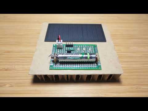
Turning once again to my store of Ikea cardboard packaging for an “all on display” demo build:

Performance
When the voltage generated by the solar cell falls below about 0.2V, the boost converter switches on. Here’s the waveform of the switched output driving the LED:

We’re currently having a wet season “cool spell” with overcast days and afternoon showers, and I have the unit indoors behind mildly tinted glass and a chance of direct sublight for only a few hours a day.
But even so I’m seeing the battery charge to ~1.3V during the day and drop to ~1.2V overnight. To get an even better picture of what’s going on, I used another Arduino to monitor the voltage and log the data to Adafruit IO (see LEAP#440 for more on the data logging).
I’ll keep monitoring this for a while yet - basically to find out if net/net the solar panel is able to keep the battery charged while in continuous use under variable weather patterns - but over the first full 24 hour period I’m seeing roughly what I’d expect:

Is This How They Really Make Them?
I was recently in a Bunnings store in Australia and was absolutely blown away by the range of LED solar lights on offer - from $1 to over $30 AUD.
I picked up a “s*lar lytworx” solar LED spotlight for $3.95AUD to find out if this is what’s really inside them.

And yes, the circuit I’ve demonstrated here is exactly what they contain:
- 3 LEDs
- a switch on the LED anode
- the YX805 version of the LED control chip
- an inductor (green - blue - black - silver, so I think 56µH)
- a solar cell
- and a 300mAh NiCad battery
The solar cell and battery are pretty small - but this was being sold on the Queenslad coast, where I’m sure there’s ample sunlight to keep these charged year-round.
