
#542 DIY Foot Switch
A DIY 4-channel foot switch with tri-colour LEDs suitable for use with a microcontroller.

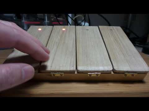
Here’s a quick demo..
Notes
I’m planning some projects where I’d like to use foot switch input, so I thought I’d fashion a device that was flexible enough for reuse.
It’s a simple plan:
- 4 independent foot switches
- a common anode RGB LEDs on each switch for state indication
- a 74HC595 shift register pipeline for LED control that can be driven with SPI
LED Control Design Notes
The RGB LEDs are capabable of complex colour mixing if used with independent PWM on each RGB colour, however for this application I plan to use each LED to indicate 4 states (red - green - blue - off).
I chose LED control with two 74HC595s for a couple of reasons:
- provides 16 bits of independent on/off control of each colour of the 4 LEDs (see mapping below)
- simple SPI control
- I’m using the HC variant so that the unit can work with 3.3 and 5V power levels
- ample source/sink current capabilites on each pin (±25mA max)
Note that since the LEDs I have are common anode, registers operate with active low logic.
The register mapping for my particular wiring scheme:
| bit | LED# | color |
|---|---|---|
| 0 | - | |
| 1 | - | |
| 2 | 3 | red |
| 3 | 3 | green |
| 4 | 3 | blue |
| 5 | 2 | red |
| 6 | 2 | green |
| 7 | 2 | blue |
| 8 | - | |
| 9 | - | |
| 10 | 1 | red |
| 11 | 1 | green |
| 12 | 1 | blue |
| 13 | 0 | red |
| 14 | 0 | green |
| 15 | 0 | blue |
Input Switch Design Notes
Each pedal has a tactile limit microswitch with an additional compression spring to prevent overworking of the switch.
Switches are wired with a pull-down resistor, and pull the output high when depressed. I haven’t added any debouncing on the switches (yet), as seems adequately handled in hardware. A ~100nF in parallel with the pull-down resistor would probably be my first choice if I find spurious activations becoming a problem.
Schematic
Showing the wiring of the LEDs and switches. The naming convention I’ve used for the hardware and code is that the LED and switch modules are numbered left to right from 0 to 3.


Construction
Assembling the parts:
- the main structure is an old kitchen spice rack, cut in half on the diagonal to form the basic “foot rest” shape
- some nice soft wood pieces for the pedals (cedar?), scavanged from a sake bottle presentation case. In the picture, I’ve already cut them to size.
- 4 hinges for the main pedal attachment
- 4 tactile limit microswitch
- 4 compression springs to offload some of the impact on the microswitches
- 4 RGB LEDs (not shown - I ony decided to add them after taking this picture)

Installing the pedals and swithes. The hinges turned out to be a bit cheap and nasty and it took a few experiments to find an orientation that would allow the pedals to press completely down.

The switch and LED circuitry is on a small piece of protoboard with a pin header for simple attachmentto a microcontroller. All installed:

Demonstration Code
The FootSwitch.ino sketch is an example of how to use the foot switch:
- updating the LED states with a simple 2-byte
shiftOut - scanning the 4 switches for activation
The code does a very simplistic scan of the switch state. There are better approaches for a real project, such as using the EnableInterrupt library to attach pin change interrupts on each pin.
Credits and References
- 74HC595 Datasheet
- RGB LED Common anode - example from an aliexpress seller
- tactile limit microswitch - example from an aliexpress seller