
#800 IR Photodiodes
Investigating and testing infrared (IR) transmission between IR LEDs and IR photodiodes. Tested with CHANZON-brand IR Emitter and Receivers (with a note about PT334-6C part confusion).
Notes
Infrared transmitters (LEDs) and receivers (photodiodes) are widely available in 3mm and 5mm through-hole tuned for 850nm or 940nm for example from this aliexpress seller.
See also:
- The Art of Electronics 12.6.1 Photodiodes and phototransistors (3rd Edition).
- Infrared and Photodetectors WEbinar by DigiKey with Würth Elektronik
Components
The aliexpress seller provided the following specification for their IR transmitters and receivers:
- Brand: CHANZON
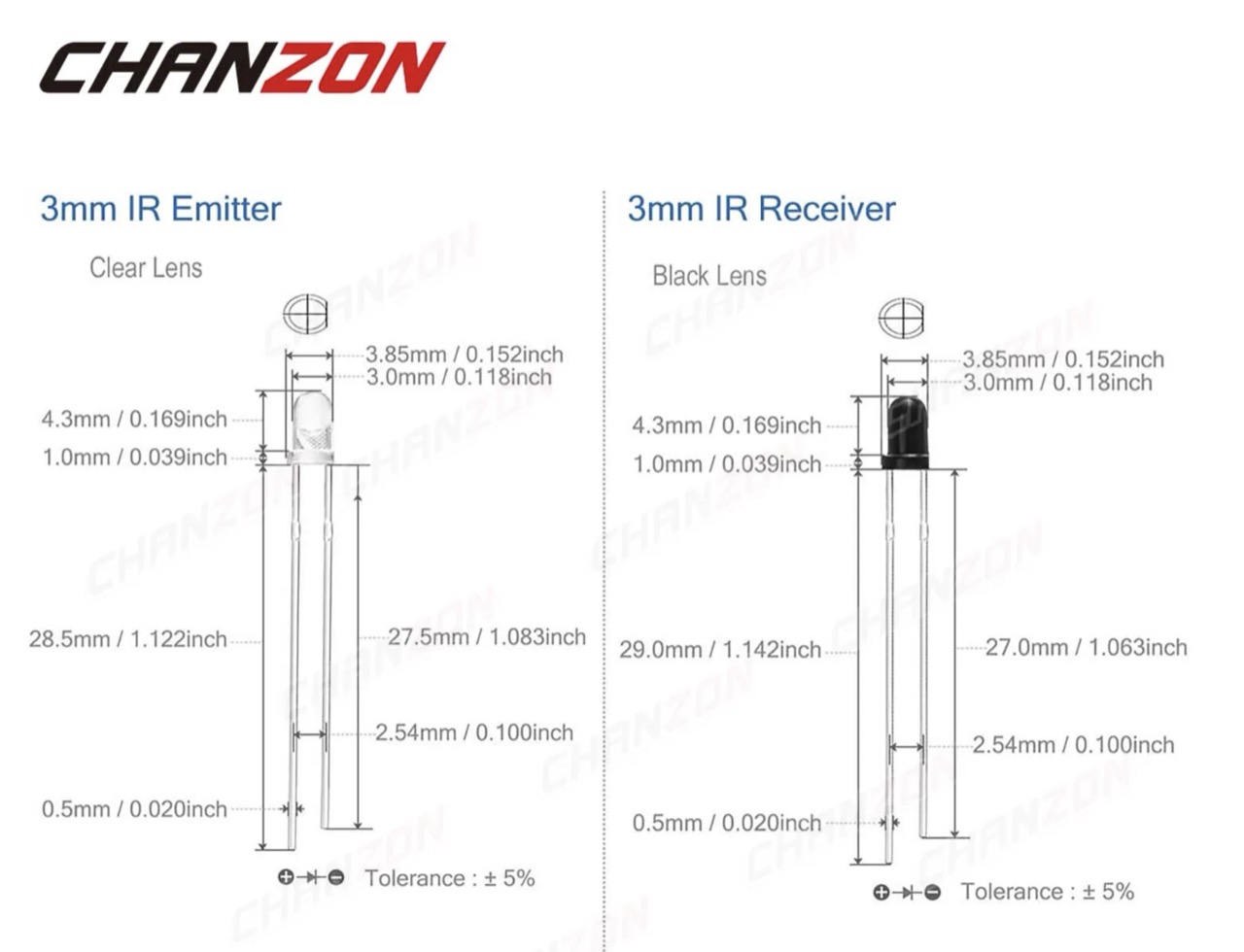
- Lens Size: 3mm / 5mm / 10mm Diameter
- Lens: Clear Lens (transmitter) / Black Lens (receiver)
- Emitting Color: IR Emitter 850nm/IR Emitter 940nm / IR Receiver 940nm
- Luminous Intensity: Invisible Light
- Emitting Angle:
- 60 Degree (850NM IR Emitter)
- 45 Degree (940NM IR Emitter)
- 30 Degree (940NM IR Receiver)
- Forward Voltage:
- 1.4-1.6V (850NM IR Emitter)
- 1.2-1.5V (940NM IR Emitter)
- Current: 20mA
- Polarity: Anode (Longer Part); Cathode (Shorter Part)
Note concerning “PT334-6C” Parts
Several vendors (Everlight being the best-known) sell the PT334-6C as a clear-lens NPN phototransistor. For example, see the PT334-6C datasheet (digikey).
However there is also some confusion caused by a number of suppliers (especially on AliExpress/eBay/LCSC 3rd-party listings) selling a device called PT334-6C, but it is actually an IR LED, not a phototransistor.
It is not really possible to visually distinguish the parts. Generally: unless the part comes with a datasheet clearly identifying it as a phototransistor, assume it is most likely an IR LED.
IR LEDs (Infrared Light-Emitting Diodes)
What they do:
- Emit light in the infrared spectrum (typically 850–950 nm).
- Similar to visible LEDs but optimized for IR output.
- Can be clear or tinted; clear lenses allow more efficient IR emission.
Key points:
- Forward-biased → emits IR photons
- Narrow spectral range, often centered near ~940 nm
- Very fast switching (tens of MHz for good emitters)
- Used as transmitters in sensing or communication systems
IR Photodiodes
What they do:
- Detect IR light and convert it into an electrical signal.
- Photodiodes operate in photovoltaic (solar-cell-like) or photoconductive (reverse-biased, fast) mode.
- Phototransistors are more sensitive but slower (because of internal gain).
Key points:
- Reverse-biased → produces current proportional to incident IR light
- Spectral response typically matches IR LED wavelengths (850–950 nm)
- Clear packages maximize sensitivity
- Phototransistor variants provide higher gain at the cost of speed
Summary
| Feature | IR LED | IR Photodiode | IR Phototransistor |
|---|---|---|---|
| Function | Emit | Detect | Detect (amplified) |
| Biasing | Forward | Reverse | Reverse |
| Speed | Very fast | Very fast | Moderate |
| Sensitivity | N/A | Low–Medium | High |
| Use as detector? | Yes (weak) | Yes | Yes |
Typical applications
- remote controls
- IR data communication (IrDA, legacy systems)
- Proximity sensors
- Break-beam detectors
- IR interlocks
- Night-vision illumination (CCTV, security cameras)
- Optical encoders (quadrature disks, motor feedback)
- Line-following robots
- Gesture sensors
- Optical flame and smoke detectors
- Barcode scanners
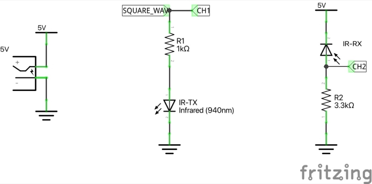
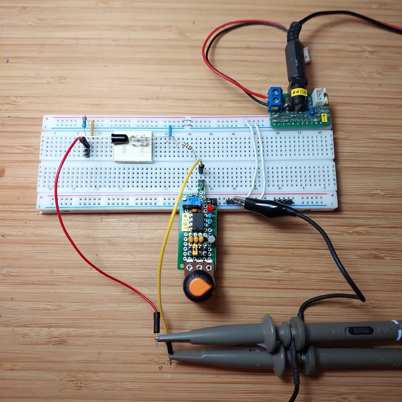
Circuit Design
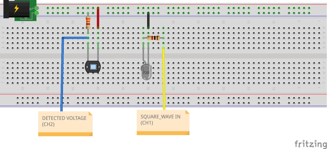
The test circuit is a simple setup between transmitter and receiver:
- a square wave generator drives an IR LED
- I am using LEAP#791 555 Breadboard Pulse Generator for this (not shown in the schematic)
- the voltage across the IR Photodiode is traced with an oscilloscope
Designed with Fritzing: see ir-photodiodes.fzz.
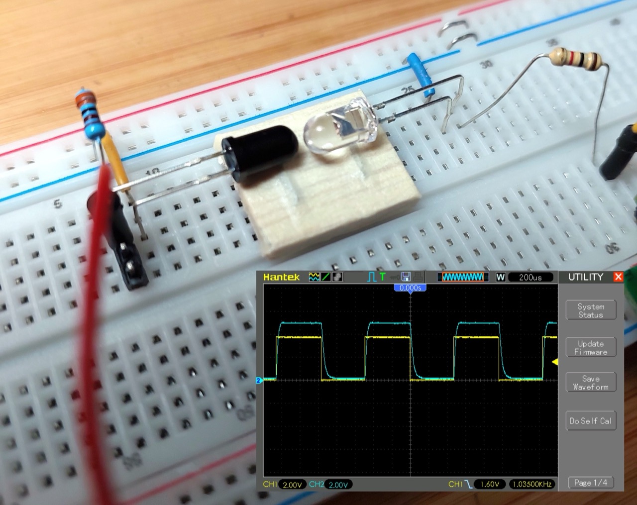
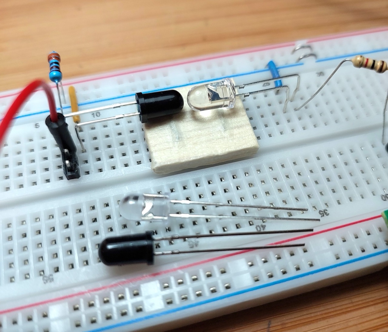
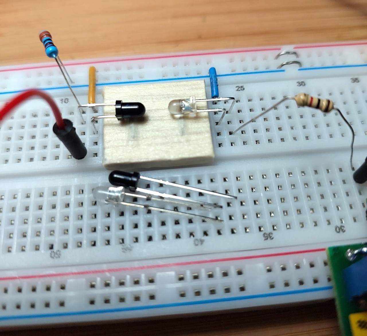
Testing on a breadboard:
- the clear component is the IR LED transmitter. It is used like other LEDs.
- the black component is the IR photodiode receiver. It is used “reverse-biased”.
Testing with 5mm Components
The following scope traces show test results at varying frequencies:
- CH1 (Yellow) - input square wave
- CH2 (Blue) - IR photodiode voltage response
At 100Hz, we see a perfect reproduction at the receiver:
At 1kHz, we see some slew appearing at the receiver:
At 20kHz, the received signal is significantly distorted:
Testing with 3mm Components
The following scope traces show test results at varying frequencies:
- CH1 (Yellow) - input square wave
- CH2 (Blue) - IR photodiode voltage response
At 100Hz, we see a perfect reproduction at the receiver:
At 1kHz, we see some slew appearing at the receiver:
At 20kHz, the received signal is significantly distorted:
Credits and References
- 100Pcs 3mm 5mm IR LED Diode Transmitter Receiver 850nm 940nm Infrared Photodiode Phototransistor Emitter Lights Emitting Bulb - aliexpress seller
- The Art of Electronics 12.6.1 Photodiodes and phototransistors (3rd Edition).
- Infrared and Photodetectors WEbinar by DigiKey with Würth Elektronik
- https://en.wikipedia.org/wiki/Photodiode
- https://www.build-electronic-circuits.com/photodiode/
- https://www.electronics-tutorials.ws/diode/photodiode.html