
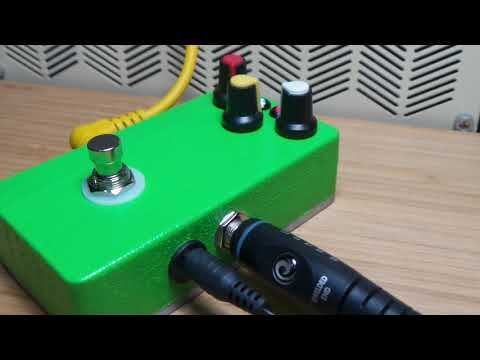
#461 The Goblin
The Goblin is what I’m calling my remake of the classic Ibanez Tube Screamer 808, after researching how the circuit works and common modifications.

Here’s a quick demo; just a sound check/smoke test..
Notes
I remember lusting after an Ibanez Tube Screamer back in the day - they really were the stuff of legend. The most famous is perhaps the TS-808.
General Guitar Gadgets have been offering a replica of the Tube Screamer 808 as a kit: the ITS8. I haven’t built that kit yet, as first I wanted to study and breadboard the circuit.
TS-808 Design
The most complete investigation of the design of the Tube Screamer I have found is R.G. Keen’s The Technology of the Tube Screamer - well worth a read. My notes that follow are in part a summary of my reading with some additional clarifications (for my own benefit).
A number of folks have redrawn the original schematic. Here’s a pretty complete and (I think) accurate one by Steve Cerutti:
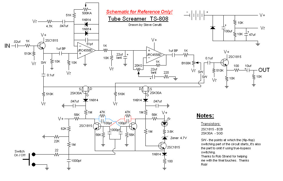
The circuit breaks down into a number of stages/sub-systems:
- Input buffer
- Clipping Amp
- Tone/volume control
- Bypass switching
- Output buffer
- Power
Input Buffer
- A typical guitar signal will be 30 to 100mV for most pickups when the string is picked, trailing off as the note decays.
- emitter follower with a cheap high-gain, low-noise NPN - 2SC1815 with ß ~ 100
- no gain (i.e. gain = 1)
- high input impedance (essentially ~ 510kΩ)
- output feeds two stages:
- clipping amp
- dry side of the bypass
Clipping Amp
- variable gain non-inverting op-amp with tricks to shape the clipping amount and frequency.
- originals use the JRC4558 - because it was “cheap”. May be replaced by other dual op-amps but whether the result suffers is a matter of opinion.
- input is biased to AC ground with ~10kΩ.
- gain = 1 + Zf/Zi
- Zf is the equivalent impedance of the feedback network
- Zi is equivalent impedance to ground
Zi comprises 4.7KΩ resistor and 0.047µF capacitor. When capacitor impedance equals the resistor, gain falls off towards 1.
- high pass filter with corner frequency of 1/(2πRC) = 720Hz
- below this, approaches no gain
- above this, gets the gain of the distortion stage
Zf is the parallel combination of the clipping diodes, capacitor and drive-control resistors
- diodes clip the signal for each polarity (with a small linear region)
- 51pf capacitor across the diodes softens the corners of the clipped waveform
- above 720 Hz, the gain resistor varies gain from about 1 + (51kΩ/4.7kΩ) = 12 to 1 + 551kΩ/4.7kΩ = 118
Tone/volume control
The gain stage feeds the tone/volume stage via a low pass filter with a roll-off from 1/(2πRC) = 723Hz
The tone control is a high pass RC filter with a roll-off at 1/(2πRC) = 3.29kHz. Depending on the tone pot position, this either affects:
- input signal, shunting high frequencies to ground (treble cut)
- feedback signal, shunting high frequencies to ground (treble boost)
Uses the second JRC4558 op-amp as a non-inverting buffer.
Volume control is a conventional arrangement of 100kΩ pot that progressively shunts the output to AC ground.
Bypass switching
Can this be filed as “unnecessarily over-engineered”?
The original design uses a discrete JFET flip-flop circuit to switch the clipping and tone/volume stages in or out of the signal path, leaving the input and output buffer stages in circuit. Most variants or remakes of the Tube Screamer replace this with true bypass switching.
Output buffer
Similar to the input buffer, another emitter follower with a 10K emitter resistor, and 510kΩ bias from the AC ground.
The output from the emitter is tapped with a series resistor and 10µF coupling capacitor, then a shunt resistor to ground. The values of these resistors is one of the main differences between Tuber Screamer models.
The TS-808 uses an unusually low 10kΩ shunt resistor and 100Ω series resistor. Other models use a 100kΩ shunt and 470Ω series resistor.
Power
The circuit expects a 9V supply and uses a voltage divider with smoothing capacitor to establish an AC ground at ~4.5V. Conventional power supply arrangements may be used, but not shown completely in the schematic:
- 9V battery clip with external 9V supply bypass
- reverse polarity protection diode
- power to ground connection switched by the input jack i.e. power on when you plug in an instrument lead
Common Modifications
The following summarises some of the common modification possibilities. More are covered in The Technology of the Tube Screamer.
True Bypass
JFET flip-flop bypass eliminated, and true bypass of the entire signal path switched with a 3PDT foot-switch.
Component Modernisation
Input/output buffer transistor substitution:
- Original used the 2SC1815, but this is not particularly critical. Key characteristics:
- ß: 70-700 (typically ~300 in the TS-808 configuration)
- Noise figure 1dB at 1kHz
- Can be replaced with newer components with similar gain and perhaps even better low-noise performance
Options:
- 2N4401
- ß: 40-500
- 2N3904:
- ß: 100-400
- Noise figure 5dB at 1kHz
- might be a bit noisy as a replacement
- 2N5089
- ß: 450-1800
- Noise figure 2dB at 1kHz
- Low noise, but increased gain(?) might need compensation
- S9014
- ß: 60-1000
- Noise figure 0.9dB at 1kHz
- looks like a great alternative
Clipping diode substitution:
- Original used the 1N914
- Can be replaced with newer components e.g. 1N4148
Op-amp Substitution
Original used the JRC4558. It was originally chosen for non-aesthetic reasons (cheap and available!), but it’s particular role in shaping and texturing the output remains very subjective.
Some possible replacements, either for availability or aesthetic reasons, include:
| Component | Notes | Tested? |
|---|---|---|
| NJM4558 by New Japan Radio Company | Used by Ibanez in some Tuber Screamer models/later models | |
| RC4559 by Texas Instruments | ||
| NJM4556 by Japan Radio Company. | Sound signature of the original with extra dynamics and attack | |
| TLC272 by Texas Instruments. | It has a nice, complex distorted sound | |
| TL072 by Texas Instruments, ST Microelectronics, and SGS Thomson Microelectronics | ||
| TL062 by Texas Instruments, ST Microelectronics, SGS Thomson Microelectronics, and Motorola | ||
| TL082 by National Semiconductor, Texas Instruments, ST Microelectronics, and Motorola | ||
| LM1458 by National Semiconductor and Fairchild Semiconductor | ||
| LM833 by National Semiconductor,ST Microelectronics, SGS Thomson Microelectronics, Motorola and ON Semiconductor | ||
| OPA2107 by Analog Devices. | Rounder sound, makes it ideal for blues players | |
| OP275 by Analog Devices | ||
| OPA2604 by Burr-Brown and Texas Instruments | ||
| TLC2272, TLC2202 by Texas Instruments | ||
| LT1213 by Linear Technology | ||
| MC33078 by Texas Instruments. | With very nice highs |
Increased Input Impedance
Some variations include an additional 1.5MΩ shunt resistor in front of the input buffer. I think this is mainly to boost input impedance which may be useful for more modern pickups. I haven’t included it in my build, as it appears to make no difference with the guitars I have tried with the pedal.
Fat Bass
The original circuit has pronounced mid range boost that increases as the drive control is turned up. Improving bass response is a common goal of modifications, including:
The frequency response is largely determined by the equivalent impedance to ground in the clipping amp. The factory components (4.7KΩ resistor and 0.047µF capacitor) form a high pass filter with corner frequency of 1/(2πRC) = 720Hz.
Changing the capacitor value shifts the frequency. Common alternatives:
| Capacitor | Corner Frequency |
|---|---|
| 0.047µF | 720 Hz |
| 0.1µF | 339 Hz |
| 0.22µF | 154 Hz |
| 0.47µF | 72 Hz |
| 1.0µF | 34 Hz |
Keeley 808 Reissue Modifications
Keeley have produced a number of effects based on Tube Screamer designs (though it appears none on offer at the moment). It appears that some of the modifications made include the following:
- Equivalent impedance to ground in the clipping amp switched to 2.4kΩ in series with 0.1µF yielding a corner frequency of 663Hz, down from 720Hz.
- Tone control roll-off increased to 4.02kHz, up from 3.29kHz
- Fixed gain feedback resistor reduced from 51kΩ to 20kΩ, reducing the minimum gain to 5.3, down from 12
Breadboard Build
The circuit works quite well on a breadboard (although it does pickup quite a bit of noise). I used this to evaluate various modifications, but ultimately decided to go with a very stock version of the circuit with just a couple of component changes when compared to the original Tube Screamer circuit, namely:
- R2, R12 560kΩ (instead of 510kΩ), since this is what I had on-hand
- C4 50pF (instead of 51pF), since this is what I had on-hand
- Q1, Q2 S9014 (instead of 2SC1815)
- 3mm white LED for the power indicator, with a 10kΩ current limit resistor (since it is a super-bright LED)
- 3mm red LED for the effect-enabled indicator, with a 3.3kΩ current limit resistor


Protoboard Build and Case
Since the circuit was working well, I transferred to a protoboard build and mounted it in a 1590B effect pedal case. The end result is excellent. When mounted in a case, the effect has low-noise and works just like the real thing.
The final build features:
- true bypass with a 3PDT switch
- 9V external power (centre-negative) that bypasses optional internal 9V battery clip
- master power switch wired via the input jack (i.e. unit only powers on when a mono plug inserted in the input)
Here are my notes on the layout I used:

Close-up of the completed protoboard:

Final test before putting in the enclosure:

Aluminium 1590B case:

All the components ready to install after giving the enclosure a stippled-green point job:

Parts installed:

Ready to rock:
Credits and References
- “Ibanez”, “Tube Screamer”, “TS-808”, “TS5”, “TS-9” and “TS10” are trademarks of Ibanez.
- ITS8 - Ibanez Tube Screamer 808 replica by GeneralGuitarGadgets
- The Technology of the Tube Screamer
- JRC4558 Analysis
- S9014 datasheet
- ..as mentioned on my blog