
#353 D Flip-Flop
Building a clocked D Flip-flop with 74LS00 NAND gates.

Notes
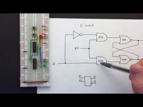
The LEAP#348 DLatch project demonstrated how to build a “data latch” with NAND gates. It’s operation is asynchronous however - meaning while enabled, the output changes as inputs change.
For digital logic circuits however, it is often preferred to have synchronous changes - meaning the outputs only change on a definitve part of a clock cycle. These are usually referred to as flip-flops, to distinguish them from asynchronous “latches”.

The D flip-flop circuit here is only slightly modified from the latch circuit:
- same NAND-gate construction
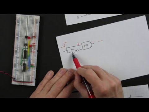
- but the enable input is tied to a clock source, with an RC circuit to acta as a rising-edge detector
As a result, output changes only occur on the rising edge of the clock.
As a clock source, I’ve wired up a simple 74LS14 Schmitt oscillator, with a pretty slow frequency of around 1.77Hz.
The edge detector is an RC integrator with a time constant of 0.1ms.
To demonstrate the flip-flop behaviour, an Arduino is feeding a data signal at around 10Hz (100ms period). This is not synchronised with the clock (enable) input, so results are somewhat randomised, allowing for all combinations of inputs to be tested.
Ben Eater’s Tutorials
Great explanations of the D latch and D Flip-Flop..
Performance
Channel connections for the following traces:
- CH1 (Yellow) - Q output
- CH2 (Blue) - clock/enable oscillator (unfiltered)
- CH3 (Red) - clock/enable trigger (filtered)
- CH4 (Green) - D input (from Arduino)
This first trace shows output Q transitioning from low to high. Note:
- occurs on the leading edge of the clock/enable pulse
- when data input is high
- does not reset on the falling edge of the clock
- does not reset when data input falls

This second trace shows output Q transitioning from high to low. Note:
- occurs on the leading edge of the clock/enable pulse
- when data input is low
- does not reset on the falling edge of the clock
- does not reset when data input rises

Construction


Credits and References
- 74LS00 datasheet
- 74LS14 datasheet
- D flip-flop - wikipedia
- RC time constant - wikipedia
- ..as mentioned on my blog