
#186 Asynchronous JK Counter
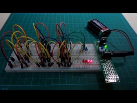
An asynchronous 4-bit counter built with JK Flip-Flops.
Here’s a quick video of the circuit in action:
Notes
This circuit uses 4 JK flip-flops set up for the “toggle” mode to implement an asynchronous 4-bit binary counter.
I’m using two 74LS73 chips for the flip-flops (each has two flip-flops). These also support a “clear” input, but since I’m not using that, all the CLR inputs are pulled high.
The “toggle” mode corresponds to the state where both J and K inputs are high. In this situation, the output will invert on the clock pulse (falling edge for the 74LS73).
A low-frequency 555 Timer astable oscillator provides a clock pulse of around 1.226 Hz, and so it is possible to follow the counter with the human eye.
Performance
Here’s a logic trace captured with the clock souped up to 470Hz.
- Logic channel D0 is the clock signal, also traced on CH1
- Logic channels D1, D2, D3, and D4 are the outputs from LSB to MSB

How Asynchronous is it?
The “asynchronous” description of the counter reflects the fact that the output transitions are not all synchronised to the same clock signal.
- only the first flip-flop is directly triggered by the input clock signal
- subsequent flip-flops are clocked by the output of the previous stage
For display purposes (like this circuit), this is not an issue. But if the counter is in turn an input to subsequent digital logic stages, the lack of synchronisation may raise havoc due to the rippling changes.
There is a “synchronous” version of this circuit - see LEAP#320 for this circuit.
Here’s a trace of 4 digit signals captured in analog with the clock souped up to 470Hz:
- CH1 is digit D3 (per the schematic) (MSB) - used for triggering on the falling edge, so we see all digit transitions together
- CH2 is digit D2 (per the schematic)
- CH2 is digit D1 (per the schematic)
- CH2 is digit D0 (per the schematic) (LSB)
The ripples are clear, taking place over about 42ns:

Construction


Credits and References
- 74LS73 datasheet - Dual JK Flip-Flop with Clear
- CD4096 datasheet
- Sequential Circuits - Asynchronous Counters
- Basic Flip Flop Applications - Columbia Gorge Community College
- JK Flip Flops - Columbia Gorge Community College
- JK Flip Flop Examples - Columbia Gorge Community College
- Binary Counter Using J K Flip Flops
- Digital Electronics – Counter Circuits
- ..as mentioned on my blog