
#452 CD4046 Mains-Linked PLL
A 50/60Hz oscillator locked to mains power frequency using a CD4046 PLL.

Notes
The CD4046 is common starting point for learning about phase-locked loops. It is essentially a “toolkit” chip, comprising independent sub-systems including:
- two types of phase detector
- VCO
My objective here is to learn a bit about designing PLLs using the edge-controlled phase comparator in the CD4046. To spice things up a bit, I’ll use the circuit to produce a square wave locked in phase and frequency to the mains power supply - 230V 50Hz at home, but the circuit will work for 60Hz and lower voltages too.
About PLLs
#60: Basics of Phase Locked Loop Circuits and Frequency Synthesis, w2aew
Circuit Design
- AC pulse detector produces a 5V signal input to the phase comparator
- CD4046 Phase Comparator II, compares phase of the input signal to the VCO output
- Low-pass Filter to smooth and dampen the comparator output to driver the VCO
- CD4046 VCO
- CD4011 NAND is used as an inverting buffer for the VCO output
Mains Interface / AC Pulse Detector
A 4N35 opto-coupler is used as essentially a half-wave rectifier to convert the AC input signal to a low-voltage pulse train approaching a square wave.
A simplistic approach is possible because I’m not trying to tap the mains supply to also power the digital circuit:
- a series of resistors to drop the voltage and limit current to around 2mA
- 4N35 opto-coupler
- reverse-polarity diode across the opto-coupler, so that it only activates on half the cycle
I’m using a 12V AC power supply for testing purposes. For this supply, the voltage is dropped across a single 10kΩ resistor and produces a strong 60% duty cycle output on the opto-coupler.
In the final build a mains connection has the voltage is dropped across ~200kΩ (3 x 68kΩ resistors in series). I don’t have datasheets for my 1/4W resistors, and I suspect they may be fine with ~230V. But putting 3 resistors in series reduces the voltage across each individual resistor, and protects against any failing closed circuit.
Note: with these resistor values, I am driving the opto-coupler reasonably hard so it turns “on” close to when the AC signal cross the zero-point. However there is at least a diode drop and rise time involved that corresponds to some lag, and this cascades through the PLL. So while the PLL output signal will be “locked” to the AC signal, it does have a fixed but non-zero phase offset that I haven’t designed out of the system.
Phase Comparator
CD4046 Phase Comparator II is used, which produces a tri-state output:
- high when signal is leading the VCO output / comparator in
- high impedance when signal is in phase with VCO output / comparator in
- low when signal is lagging the VCO output / comparator in
VCO Configuration
VCO frequency range is controlled with the combination of C1, R1 amd R2.
R2 is left disconnected/high impedance, which sets the minimum frequency to 0 Hz.
Figure 5 in the CD4046 datasheet provides a rough guide for selecting C1 and R1. I chose C1 = 100nF and R1 = 100kΩ, which should correspond to a centre frequency of around 100Hz.
In practice, the range is 0 Hz to 166Hz. That’s a reasonable range for covering mains frequencies, expected to be 50/60Hz.
Some measurements to determine the actual VCO gain:
| VCOin | Frequency |
|---|---|
| 4.96 V | 165.5 Hz |
| 3.2 V | 99.5 Hz |
| 2.0 V | 49.1 Hz |
So very roughly a VCO gain, KVCO, of 247 radians/sec/volt.
Low-pass Filter
OK, this gets interesting and math-heavy. The CD4046 is notorious for not having a straight-forward LP filter configuration, especially with Phase Comparator II.
In section 9.29 of the Art of Electronics, there is a design example that I’m still trying to pull apart.
My design thinking so far:
Low-pass filter comprises C2, R3 and R4:
- R3C2 time constant drives the response time (smoothing)
- R4/R3 ratio influences the dampening
Given a 50 to 60 Hz mains frequency, choosing LP unity gain of around 2 Hz.
Choosing C2 = 2.2 µF and R4 = 220kΩ, zero/breakpoint of the LP filter is around 2πR4C2 = 0.33Hz
Using a starting guide that suggests R3 ~= 5 * R4, I choose R3 = 1MΩ.
So while I don’t have the full rigorous derivation of the filter, these component values turned out to produce a well-locked VCO signal that is stable and relatively immune to noise.
Construction
The final schematic:

First built on a breadboard, with a 12V AC input to keep things low power.

In this pic, I’m actually using a CD4069 inverter to buffer the output:

For the final build:
- transferred to protoboard
- two sections with a good air-gap across the opto-coupler
- mains cable with 2-pin (unearthed) plug
- project case with a small cut-out for access to power, LED and signal pins
Signal pins exposed:
- In = the raw signal from the opto-coupler
- Out = the buffered VCO output

Rough sketch of the protoboard layout plan:

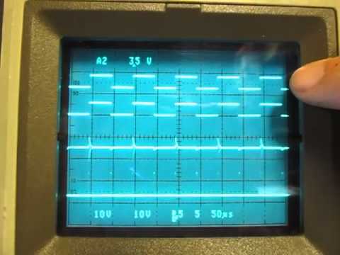
Test Results
A very clean 50 Hz square wave output
- CH1 (Yellow) - synchronised output wave
- CH2 (Blue) - incoming wave from the opto-coupler

Credits and References
- CD4046 Datasheet
- CD4011 datasheet
- 4N35 datasheet
- The Phase-Locked Loop
- The Art of Electronics - 9.27 PHASE-LOCKED LOOPS, 2nd Edition p641
- CMOS Phase-Locked-Loop Applications - TI Application Report
- CD4046B Phase-Locked Loop - TI Application Report
- 74HC4046 PHASE-LOCKED-LOOP WITH VCO
- Frequency of the power grid - microcontroller project with some interesting results