
#162 BoostBuckConverterModule
Quick test of an LM2577S/LM2596S Boost/Buck Converter Module
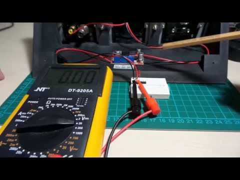
Here’s a quick video demonstrating the basic control and the constant current issue:
Notes
I got an LM2577S/LM2596S Boost/Buck Converter Module to see if it might be any good as a current-limited power supply for prototyping, and also to investigate the buck/boost circuit it uses in more detail.
It has a handy output voltage range of 1.25-25V and constant current limiting between 0-2A.
Since the voltage/current/charging indicator controls are trimmers on the PCB, and because there is no integrated display of voltage or current, it is fine for applications where the voltage/current settings need only a one-time adjustment. Or with a bit of modding it could be the core of an adjustable power supply unit.
Here’s the module annotated with connections, controls and indictors:

Constant Voltage Control
With an input voltage of 12V, I measure that actual output voltage range as from 1.24V to 26.6V (no load). The selected output voltage range appears to remain very stable under load.
Constant Current Control (with WARNING)
At first, I thought the constant current control was not working. But after a bit of experimentation, I discovered I was being mislead by what appears to be a pretty important design flaw:
the constant current control only takes effect if the load is connected after the unit is powered up
i.e. if you have a circuit connected (or an ammeter for short-circuit current test) when you turn on the input power, the current will not be limited according the the constant current setting. But if you turn on the unit first, then connect the load, the preset constant current setting will take effect.
For battery charging applications, this may not be a big deal. But for powering a fixed installation (like a LED array as suggested in the application notes), this would appear to make the power supply pretty useless, and a good way to fry some LEDs if not careful. My advice would be to design the circuit without relying on the current-limiting feature of the power supply. But then why use a power supply with a “constant current” feature? Good question.
I don’t have enough experience with buck/boost modules to know if this is unusual or even just a problem with my specific unit. Or perhaps I’m just doing it wrong?
I posted this video to demonstrates the behaviour.
The PCB is too dense and multi-layed for me to easily trace it out to see if there is an understandable design flaw. I might see if I can find some similar modules to compare their behaviour. I’m also contacting the seller to see if they can tell me more.
A 5V 150mA Power Supply Setup
For now, I’ve just mounted the unit as a 5V 150mA voltage and current-limited supply. Handy for prototyping, while protecting me from mistakes that might try to draw > 150mA and smoke some components. However the issue mentioned above means I must remember to turn on the power supply before connecting the power to the circuit. Will I always remember to do that? Hardly!
I was going to replace the voltage and current trimmers with panel-mounted pots, but with the constant-current issue clouding the picture I haven’t bothered. I think I’ll be trying some other buck/boost modules (or circuits) first.
But when connected correctly, it does work. Here is the short-circuit current measurement with Vout = 5V and 150mA preset constant current setting:

Ready for powering some experiments:

Product Specs
from aliexpress listing
Module Properties: non-isolated step-down constant current, constant voltage module (CC CV) charging module
Specifications:
- Input Voltage :4-35V
- Output voltage: Continuously adjustable(1.25-25V unload adjust)
- Output current: 3A Max(If more than 15W, please install the heat sink)
- CC range :0-2A (adjustable)
- Revolving light current: CC value * (1%-100%), default is 0.1 times
- Minimum voltage difference: 2V
- Output power: natural cooling 15W
- Conversion efficiency: 80% (the higher the output voltage, the higher the efficiency)
- Operating Temperature: Industrial (-40 degree to +85 degree) (ambient temperature more than 40degree, lower power use, or add heat sink)\
- Full load temperature rise: 45 degree
- Indicator: CC indicator is Red, charging indicator is Red, charging completed the indicator is Blue.
- Output short circuit protection: Yes, constant current.
- Connect method: Can solder on the PCB with wire directly
- Input: IN+ input Positive is, IN- input negative
- Output: OUT+ output is positive, OUT- output negative
- Module Size: 50 x 37 x 13mm
- Some application:
- High-power LED constant current driver
- Lithium batteries (including ferroelectric), 4V, 6V, 12V, 14V, 24V battery charging, nickel-cadmium nickel-metal hydride batteries (battery) charge.
- Solar panels, wind generator voltage regulator circuit board power supply, such as automatic buck regulator circuit.
Application: Battery charging
- Make sure of the voltage and current of the battery you need to charge
- Adjust the constant voltage potentiometer to make sure the output Voltage is about 5V(about).
- Use the multimeter in 10A current scale to measure output short-circuit current, and adjust the current potentiometer to make sure the output current to the expected charging current value
- The charge current of transfer lamp is default 0.1 times of the charging current (constant current value)
- Adjust the constant voltage potentiometer to make sure the output Voltage is up to floating Voltage.
- Connected to the battery and try to charging (for previous 5 steps, module input terminal is connected to power source, output load is NOT connected to batteries).
Application: LED Constant Current Driver Use:
- Make sure operating current and Max operating Voltage of the LED you need to drive.
- Adjust the constant voltage potentiometer to make sure the output Voltage is 5V(about).
- Use the multimeter in 10A current scale to measure output short-circuit current, and adjust the current potentiometer. To make sure the output current to the expected LED operating current.
- Adjust the constant voltage potentiometer to make sure the output Voltage is up to LED Max operating Voltage.
- Join LED, test (For the above 3 steps, module input terminal is connected to power source, output load is NOT connected to LED)
Credits and References
- module from seller on aliexpress
- LM2577 product info
- LM2596 product info
- Build your own Variable Lab Bench Power Supply - inspiration from GreatScott!