
#517 555 Timer Fixed-duty VFO
Using an unconventional configuration of a variable frequency 555 timer oscillator with fixed duty cycle (and precise duty cycle fine adjustment).

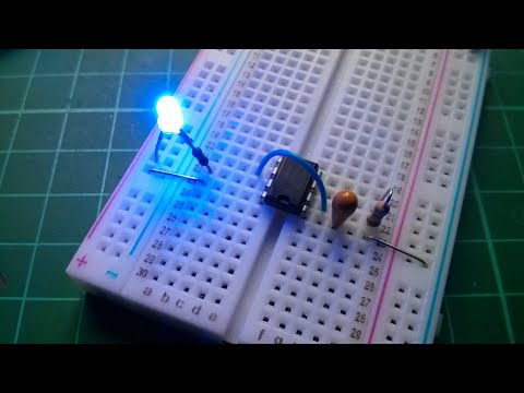
Here’s a quick demo:
Notes
The conventional configuration of the 555 timer - such as in LEAP#016 Astable Oscillator - suffers from a correlation of frequency and duty cycle when variable timing elements are used.
Is there an easy way to produce a variable frequency 555 oscillator with a fixed duty cycle? There are quite a few “close but no cigar” candidates, but my interest was piqued when I saw Julian Ilett’s “555 Timer LED Flasher (with weird connections)”:
I played this out on a breadboard for myself, and found that in the basic configuration, duty cycle remains solidly fixed at 60% over the full frequency adjustment range.
I’ve added a control voltage adjustment to the version of the circuit described below, which allows duty cycle to be precisely adjusted between about 10% and 90%.
I call this duty cycle fine adjustment, because adjusting the duty does affect the frequency, but once a duty cycle has been selected, the frequency can be adjusted without changing the duty cycle.
Circuit
Duty cycle adjustment as provided by VR2: a simple voltage divider with C2 for stability, setting the upper threshold limit of the 555 via the control voltage input.


Breadboard Test
I used 1µF C1 to shift up the oscillator for an easier time-base to plot on a scope:

The default duty cycle (without any control voltage input) is 60%, VCC is 5V. The scope shows:
- CH1 (Yellow) - discharge pin - oscillates between 0V and 3.84V
- CH2 (Blue) - C1 cathode i.e. threshold/trigger pin - 1.68V to 3.36V
- CH3 (Red) - output pin - oscillates between 0V and 4.64V
- CH4 (Green) - control pin - 3.36V

With control voltage input to adjust duty cycle to 50%, VCC is 5V. The scope shows:
- CH1 (Yellow) - discharge pin - oscillates between 0V and 3.84V
- CH2 (Blue) - C1 cathode i.e. threshold/trigger pin - 1.28V to 2.88V
- CH3 (Red) - output pin - oscillates between 0V and 4.72V
- CH4 (Green) - control pin - 2.88V

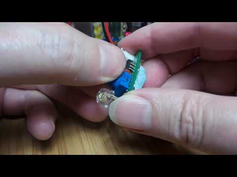
Protoboard Build
I have some new 8mm strawhat LEDs, so I thought I’d give them a go with this circuit on a bit of protoboard:
Credits and References
- LM555 Datasheet
- 555 Timer LED Flasher (with weird connections) - Julian Ilett