
#456 pease-out
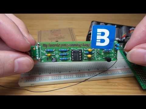
An audio voltage indicator based on the Boldport Club Pease-out, Project #32 Jan 2019.

Here’s a quick demo..
Notes
The Boldport Pease-out is another tribute to Bob Pease and the classic LM331. As designed, it implements a version of the stable-frequency oscillator desribed in a TI application note: Figure 2 Stable-Frequency Oscillator Using a V/F Converter:

The frequency of the LM331 in its standard configuration is usually proportional to Vin:
Fout = Vin / Vref * Rs/Rl * 1/(1.1 * Rt * Ct)
But the “Stable frequency” configuration has pins 2 and 7 tied together, so Vin == Vref and thus frequency becomes a function of passive component values:
Fout = Rs/Rl * 1/(1.1 * Rt * Ct)
The Pease-out sticks a 2MΩ variable resistor in Rt, yeilding a frequency range of about 2.2 Hz to 303 Hz.

I built this on a breadboard first to do a little experimenting:

Putting the output on a scope confirms a range of about 4Hz to 306Hz.


These traces also confirma that the adjustment of Rt only affects the duration of the low phase. That essentially means frequency is only indirectly adjusted by changing the duty cycle.
From the functional diagram it is clear why this is so:
- the Rt.Ct time constant governs the duration of the 1-shot timer which determins how long the output is pulled low
- where-as the Rl.Cl time constant governs the duration before the comparator triggers the 1-short time, determining how long the output remains pulled high

Amped up to about 1kHΩ, here’s a capture showing the corresponding charge cycles.
- CH1 (Yellow) is the output pulse train from Fout
- CH2 (Blue) is the voltage at pin 5 - demonstrating the Rt.Ct time constant at work controlling the “low” period
- CH3 (red) is the voltage on pins 1 and 6 - demonstrating the Rl.Cl time constant at work controlling the “high” period

LM331 Design Rules
Some basic design rules/guidelines I’ve picked up from the datasheet and experiments:
- Cl should be approx 10 x Ct
- Rl must be larger than Rs
- the Rt.Ct time constant governs the duration of the 1-shot timer which determins how long the output is pulled low
- the Rl.Cl time constant governs the duration before the comparator triggers the 1-short time, determining how long the output remains pulled high
- Rin should roughly match Rl to cancel comparator bias
- Vref = 1.9V. In some frequency equations there will be a mystery “2.09” value. This is actually Vref and the 1.1 term already reduced: 1.9 * 1.1 = 2.09.
Parts
The Boldport kit … lovely PCB and quality components as always:
| Part | Qty |
|---|---|
| LM331 IC, TI LM331N/NOPB | x1 |
| N-channel MOSFET transistor, Fairchild 2N7000_D26Z | x1 |
| 5mm red LED, CREE C503B-RBS-CW0Z0AA1 | x1 |
| 2MΩ trimmer, Suntan TSR-3296Y-205R | x1 |
| 15KΩ resistor, Multicomp MF25 15K | x6 |
| 16-pin IC socket, TruConnect 22-0107 | x2 |
| 10µF electrolytic capacitor, Multicomp MCUMR16V106M4X5 | x1 |
| 0.1uF, Suntan TS170R2A104KSBBA0R | x1 |
| 1uF, Suntan TS170R1H105MSBFA0R | x2 |
| 10-pin header, Multicomp MC34739 | x1 |
| Lovely PCB | x1 |


Hacking the Kit for a New Application
This is the last of the “classic series” of monthly kits (Boldport Club continues .. but just not on the gruelling monthly schedule), so I could hardly just build it without contemplating a few customisations!
I finally decided to adapt it to be an audio voltage probe, requiring just a few modification.
Adding a voltage probe
This firstly meant cutting the trace between pins 2 and 7 so Vin is no longer locked to Vref.
Then I extended a voltage probe with a 33kΩ:33kΩ voltage divider. Usefully, the PCB already exposed pin 7 (Vin) on one of the side connectors, conveniently next to a ground pin. I isolated another connection for the actual voltage probe - a short length of 0.9mm copper wire.
Audio Indicator
Instead of a visual indicator, I switched to audio: the LED was replaced with a piezo transducer, and the current-limiting R2 replaced with a dead short. Since I’m just using a piezo sensor, not a buzzer unit, it needs a bypass resistor to dump the charge (I used 10kΩ).
The piezo is held to the PCB with some Boldport stickers.

Frequency Adjustment
To get frequencies into a roughly audio range, I decimated Cl and Ct to 100nF and 10nF respectively for maximum frequency of about 8kHz
Power
Finally, a micro USB connector attached to the end of the PCB for 5V power.
Revised Circuit


Credits and References
- peaseo - Boldport Product Page
- peaseo GitHub Repo - design sources including documentation
- LM331 Datasheet
- TI Application Report snoa735b
- ..as mentioned on my blog