
#411 cordwood-three
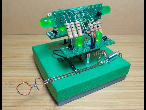
Custom build of the Boldport Club Cordwood Puzzle III, Project #25, May 2018, with an archway layout and a spring-loaded LED trigger machanism.

Here’s a quick demo of the build on a custom test jig “LED Blinky Machine”..
Notes
This is the third Boldport Club project in the Cordwood series. See my build of the first and second. Here they are all together:

The Kit
The kit arrrived in the familar brown paper


If you want to build this kit, the easiest way is to join the club and order the BoldportClub kit. But you could do it without the kit: the PCB design is open source so it is relatively easy to make an identical (or similar) set of boards, and the parts are relatively easy to obtain:
| Qty | Original Part | Mouser Equivalent |
|---|---|---|
| x6 | 220Ω 2W resistor, Multicomp MCF 2W 220R | 603-RSF2WSJR-52-220R |
| x6 | 10KΩ 2W resistor, Multicomp MCF 2W 10K | 588-OY-10K-E |
| x6 | MOSFET n-channel transistor, Fairchild 2N7000_D26Z | 512-2N7000 |
| x1 | 1µF ceramic capacitor, AVX SA305E105MARC | 80-C440C105Z5U-TR |
| x6 | 10mm green LEDs, Kingbright L-813GD | 696-SSLLX100133SGD |
| x1 | 25mm M3 female-female standoff, ETTINGER 05.03.251 | 761-M1272-3005-SS |
| x1 | 25mm M3 female-male standoff, ETTINGER 05.13.251 | 761-M2120-3005-SS |
| x2 | M3 screws, DURATOOL M38 CSSTMCZ100- | |
| x1 | 10-pin 2.54mm header, Multicomp MC34739 | 710-61301011121 |
| x5 | 6cm of 20AWG wire |
Schematic
The circuit is similar to the other cordword projects: essentially an array of LEDs with low-side NFET switches. By default, the LEDs are on with a pull-up resistor on the MOSFET gates. The gate is exposed via pin header so it can be pulled low (turning off the LED).

Construction
The conventional construction is a vertical stack. The Boldport guide outlines the construction:

I played around for a bit looking for alternatives, and settled upon an archway style which I found quite appealing;-)

So that’s working fine - I can toggle the LEDs by pulling any of the 6 gate pins low.

Here are my working notes for re-arranging the connections…

A Custom Test Jig - LED Trigger Machine
So without getting too fancy, I wanted a nicer way of mounting and testing the project. One thing lead to another, and soon I had a completely pointless LED blinking machine:
- I used the box from The Boldport Gent project as a base
- 4 x AAA in the box
- power switch
- and a spring-loaded trigger mechanism for blinking the LEDs
Close up on the trigger machnism - a bit of ad-hoc wire craft and a spring:

Power and switch connections inside the box:

Side view..

Credits and References
- Cordwood Puzzle Three - Boldport Product Page
- 2N7000 datasheet
- ..as mentioned on my blog
- ..as posted on hackady.io