
#447 Capacimeter
Measuring capacitance with old-school 555 and 4017 digital logic - a Boldport Club remix of a PEAK, Project #31, December 2018.

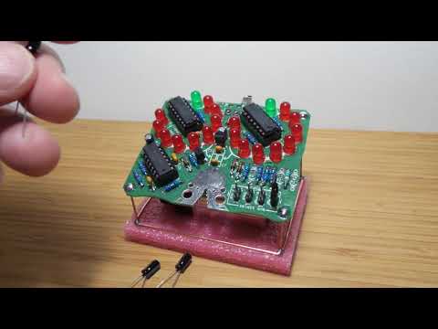
Here’s a quick demo..
Notes
Capaci-meter is a Boldport remix of a classic capacitance measurement circuit designed in high school by Jez Siddons of Peak Electronic Design.
The device takes a very interesting approach - rather than trying to measure the actual capacitance or charge time, it uses a derivative function (the capacitor’s effect on the frequency of a 555 timer) to infer capacitance.
How it Works
There’s a full write-up in the User Guide.
It is quite ingenious; here’s my paraphrasing…
Basic operation boils down to four points:
- the capacitor under test alters the frequency a “Cx-dependent” 555 astable multi-vibrator
- this gates the output of a second, Cx-independent 555 astable multi-vibrator
- CD4017 decade counters are used to count the number of pulses let through the gate
- the 4017s drive the LED display, with 10 LEDs arrange clock-face style. Two 4017s make for two-digit resolution
Finer details to note:
- the “range selector” is changing the R2 value (thus frequency) of the Cx-independent 555
- the Cx-dependent 555 counter is in “measurement” when output high:
- LEDs are disabled (by pulling LED cathodes high)
- enables the Cx-independent 555 counter
- triggers 4017 reset at the start of the pulse
- the Cx-dependent 555 counter is in “display” when output low:
- LEDs are enabled (by pulling LED cathodes low)
- disables the Cx-independent 555 counter
The schematic is from the Boldport design sources on Github:

Kit
Parts
| Reference | Qty | Description |
|---|---|---|
| R1 | 1 | 1.5M 1% |
| R2 | 1 | 150k 1% |
| R3, R7, R10 | 3 | 13k 1% |
| R3’, R5, R6, R8, R9, R12 | 6 | 1k 1% |
| R4 | 1 | 560R 1% |
| R11 | 1 | 130k 1% |
| R1’, R2’, R4’ | 3 | Not fitted (optional to adjust accuracy) |
| C1, C2 | 2 | 10uF, 10V or higher, 20%, electrolytic |
| C3, C4, C5 | 3 | 100nF, 16V or higher, 20%, ceramic, Y5V/X7R |
| C6 | 1 | 4.7nF, 1% or 5%, ceramic, COG/NPO |
| C7 | 1 | 47pF, 20%, ceramic, COG/NPO |
| C8 | 1 | 10nF, 20%, ceramic, X7R |
| D1, D2, D3, D4 | 4 | 1N4148 Signal Diode |
| U1, U2 | 2 | CD4017BE Decade Counter (Use socket!) |
| U3 | 1 | NE556 Dual Timer (Use socket!) |
| U1’, U2’ | 2 | 16 pin DIL socket (7.62mm) |
| U3’ | 1 | 14 pin DIL socket (7.62mm) |
| U4 | 1 | 78L05 5V 100mA Regulator |
| Q1 | 1 | 2N7000 N-Ch MOSFET |
| LED1-L, LED1-R | 2 | Low current or high brightness green LED, 5mm. |
| LED2-L to LED10-L, LED2-R to LED10-R | 18 | Low current or high brightness red LED, 5mm. |
| LK1, LK2, LK3, LK4 | 4 | Header pins (2 pins per header) for range selection jumper |
| JP1 | 1 | Jumper needed for header pins (only 1 jumper needed) |


Construction
Luckily the PCB was designed with standard 3.54mm spacing between jumpers, meaning a breadboard can be used to align pins for soldering:

Soldering complete, and initial test under power:


Custom Power switching and Base
I added a centre-positive barrel jack with as battery bypass and a small switch so that:
- there’s power on/off control
- and the alternative of providing external power instead of a battery
I also did a little wire-craft to make a custom base for the kit. It’s stuck to a bit of packing foam for stability and isolation.


Credits and References
- CAPACI-METER - Boldport Product Page
- CAPACI-METER GitHub Repo - design sources including documentation
- Capaci-Meter - an elektor magazine lab write-up on the circuit
- CD4017 datasheet
- 556 datasheet - two 555s in one package
- ..as mentioned on my blog