
#363 BINCO
BINCO is a little up or down “fidget” counter, Project #19 of the Boldport Club.

Notes
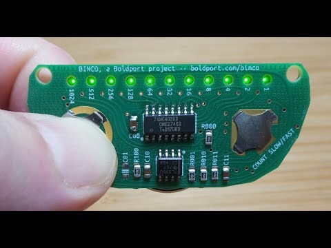
The BINCO a binary counter that can be configured to count up or down. It uses Snaptron domes as buttons (on, slow/fast and reset). The heart of the counter is a 555 timer driving a 74HC4020D 14-bit Binary Counter from which 11 taps drive some nice reverse-mount LEDs.
Parts and Unboxing

| Item | |
|---|---|
| 1x | 14-bit binary counter IC, Nexperia 74HC4020D,652 |
| 1x | 555 timer IC, TI TLC555QDRG4 |
| 11x | Reverse mount green SMD LEDz, Kingbright KPTL-3216CGCK |
| 1x | N-channel MOSFET SMD transistor, ON Semi BSS123 |
| 16x | 1.5KΩ 0805 resistors, Multicomp MCWR08X1501FTL |
| 2x | 47KΩ 0805 resistors, Multicomp MCWR08X4702FTL |
| 2x | 1µF 0805 capacitors, Multicomp MC0805F105Z160CT |
| 1x | CR2032 battery clip, Multicomp BC-2001 |
| 1x | Dome (reset), Snaptron GX05300 |
| 1x | Double action dome (count slow/fast), Snaptron DT10340N |
| 1x | Dome (on/off), Snaptron F10450 |
| 1x | PCB |
| 1x | Piece of adhesive sheet |


How It Works
The 555 timer is in an astable configuration, initially disabled.
- when “count slow” button is pressed, ti runs at around 15 Hz
- when “count fast” button is pressed, it runs at around 320 Hz
The timer provides the clock pulse to the 74HC4020D 14-bit Binary Counter. The 74HC4020D provides 12 taps of a ripple-carry chain, but the first (pin 9) is not used, probably because the chip doesn’t provide pins for the next two stages.
As always, Boldport provides a very nice infographic for the project, but here is my re-drawing of the circuit (it’s how I make sure I understand what is going on!)

Interesting:
- the “on” switch only affects the LEDs; the ICs remain powered by the battery at all times. I suspect a sneaky trick to always “remember” the last state!
- but R100 stops the 555 timer running while not “on” by pulling down the reset pin.
Construction
I decided to build the “count down” configuration, which involves making sure the LEDs point to the edge of the board, and bridging the down/right count pad.
In this configuration, R101 and IC10 are optional, so I left them off the board.


Here’s a quick demo, “fast mode”.
Credits and References
- BINCO - product page
- BINCO - on the community site
- LM555 Datasheet
- 74HC4020 Datasheet
- ..as mentioned on my blog