
#429 Boldport 3x7 Pomodoro Timer
A Pomodoro timer wire sculpture using the Boldport 3x7 display and an ATmega328.

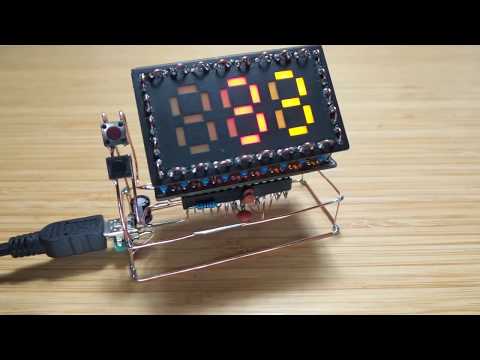
Here’s a demo of it running a 5-minute countdown (I would be surprised if anyone watches the whole thing without skipping to the end!)..
Notes
Over the years, I’ve become habituated to working in a Pomodoro style - make the day a series of tasks worked on in short blocks of time, with regular breaks. But I’ve never actually used a timer - just relied on my internal clock to work in roughly 1 hour increments.
As I was building the Boldport 3x7, it started to appeal to me as a very nice display to use for a non-distracting Pomodoro timer.
The sketch proved to be quite simple, using the LRThreeDigits library for driving the 3x7 display.
After breadboarding the idea my first thought was to make a PCB … but as there’s been a bit of Mohit Bhoite fandom in the Boldport Club recently, I was drawn into a another copper-wire sculpture. Not very ruggedized, but it does look interesting!
Now for the true test - is it actually useful? Well, I’ve started using it for real as my pomodoro timer and so far so good.
Note: the two left-most digits are minutes, the last digit is tenths of minutes. This is actually why I built my 3x7 with the yellow digit on the right;-)
Design Concept
There’s a few things I set out to achieve:
- the 3x7 displays minutes in two digits, and tenths of minutes on the 3rd digit
- the pomodoro countdown runs from at most 95 minutes, but default to start at 55 minutes (my preferred time block)
- the Arduino measures reasonably accurate time for the countdown, but I’m not going to be upset if it is a little off (less than a minute)
- before starting the count, two buttons can be used to increase or decrease the countdown respectively, in increments of 5 minutes
- when the countdown has completed, the unit will flash for a period of time
- a button press resets the app for another countdown
- if no input, go to sleep
- if sleeping, a button press wakes up and resets the application
Measuring Time
How to measure time with an Arduino? We could:
- use the
millis()function - use an external real-time clock
- use interrupts to measure increments of time
Given that timing requirements are not critical, I’m going to start by trying to base things on millis().
This counter eventually rolls-over, but since that is after ~50 days, I’m ignoring this for now.
Buttons
Buttons are connected to pins 2 and 3, using the built-in pullup resistors. Hardware interrupts on the pins are used to trigger related functions in code.
These buttons handle “up” and “down” adjustment of the countdown duration before it starts (in 5 minute increments).
Once the countdown has started, pressing either button will cancel/reset the counter.
If the application has gone into sleep mode, either button can be used for wake-up.
Pin Connections
In order to reserve pins 2 and 3 for buttons with hardware interrupts, the 3x7 is connected from pin 4 to 13:
| 3x7 Pin | Arduino Pin | Port |
|---|---|---|
| Digit 1 Sink | Pin 4 | PD4 |
| Digit 2 Sink | Pin 5 | PD5 |
| Digit 3 Sink | Pin 6 | PD6 |
| Segment g | Pin 7 | PD7 |
| Segment f | Pin 8 | PB0 |
| Segment e | Pin 9 | PB1 |
| Segment d | Pin 10 | PB2 |
| Segment c | Pin 11 | PB3 |
| Segment b | Pin 12 | PB4 |
| Segment a | Pin 13 | PB5 |
Note: this requires v1.2.0 or later of the LRThreeDigits library.
Sleep Mode
If there has been no button input for 5 seconds after the countdown is complete, the program puts the processor into SLEEP_MODE_PWR_DOWN. Since there are no additional peripherals to power, the current draw is very low in this mode. I haven’t measured it accurately yet, but according to a USB power meter it is below the ~1mA resolution of the reading.
Breadboard Prototype
To test things out by plonking an ATmega328 on a breadboard..


Wiring Up
I may do a PCB one day for a more ruggedized version, but I’m on a copper wire construction binge at the moment. I don’t have a detailed design - just some very rough sketches in a book (mainly to make sure I didn’t get my pin connections all mixed up). The actual design just came together by eye and a bit of patience;-)
The finished base ready for testing. The USB mini connector is for power only (I need to pull the chip if I want to reprogram).


With 3x7 mounted:

And powered up:

Next steps - I’m thinking about adding a mount so that I can hook the unit to the top of my monitor. Later…