
#125 Voice Level Indicator Kit
Build and investigate a commercially available “3-band voice level indicator” kit.

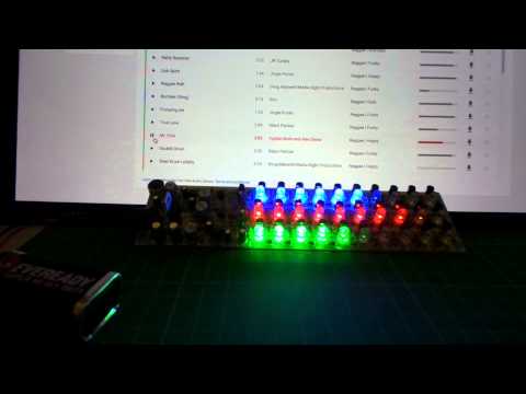
Here’s a quick video of the circuit in action:
Notes
I was inspired to build this kit by Julian Ilett’s tutorial with a similar kit - a great basic soldering instructional if nothing else.
The kit is quite a common item on ebay, bang-good, aliexpress - all the usual sites.
Performance
Soldering the kit together is quite therapeutic, and the end result is pretty decent. However there seem to be a couple of issues that could be improved:
-
It seems to bit quite a bit of “cross-talk” between the 3 LED strips. As in: trimming the pots for master control and band control will affect the whole balance of the circuit. Perhaps isolating the 3 filter circuits with say a unity gain OpAmp would help.
-
The 3 filter bands seem pretty poorly selected/tuned for a nice balanced display. Generally the low and mid range bands should be moved up a bit, and the amplification of the high band brought in line with the others.
Should I try an improved circuit? Perhaps .. a project to save for another rainy day.
Circuit Analysis
The circuit breaks down into 4 basic modules:
- power supply
- mic input and audio amp
- filter (x3)
- LED driver (x3)
Power Circuit
The input voltage of 8.5-15V is regulated down to a stable 6V by an L7806CV regulator. A 1n4007 diode provides reverse voltage protection, and chunky 220µF caps provide smoothing before and after the regulator.
My kit was missing the 1n4007. No biggy as I had some on hand (plus a umber of other components were supplied in excess. Rather than use the JST connectors provided, I replaced the power connector with a barrel jack. Since this makes reverse polarity connection extremely unlikely, I probably could have just skipped the 1n4007 and shorted the connection instead.
Audio Amplifier
Audio input is captured with an electret microphone and amplified in two stages with S9013 PNP transistors. A 50kΩ pot provides master gain control for the second stage
Filters
The amplified audio is presented to 3 filter/LED driver chains. Each filter is tuned for a specific pass-band, and has a 50kΩ pot for individual level control.
The filters seemed a bit unbalanced and it’s a little touchy to trim the individual pots for a given input level.
Taking a closer look at the filter circuits, each is a combination of two RC filters and NPN transistor to bother selectively pass frequencies and also amplify the signal. That’s a bit too complex for my entry level RC filter analysis skills, so I modeled the filters in this CircuitLab project.
If I can trust the CircuitLab frequency analysis, things do look a bit out of whack and this matches observations of the circuit:
- low-frequency bandpass is tuned too low, peaking around 10Hz!? This might explain why it seems prone to oscillate when idle
- mid-range doesn’t get much boost compared to the other bands, and again it is probably tuned too low; I think ideally it would be peaking around 1-5kHz
- high-frequency dominates, getting maximum amplification. This is what happens in practice too.


LED Driver
The three LED driver circuits are identical. A series of 1N4148 diodes provide a voltage ladder feeding 10 LED stages.
Each diode drives the base of an S9012 PNP transistor through resistor, the value of which is scaled to the voltage of the stage to hopefully drive it in the active region. The S9012 drives an LED paired with a 560Ω current-limiting resistor.
This is a bit strange .. the forward voltage of the 1N4148 is rated at 0.72V at 5mA, but can be 1V max at other currents.
On spec, it seems there would be no way to drive all 10 LEDs, since the forward voltage should be around 7.8V (10 x 1N4148 & 1 x S9012) - far in excess of the 6V supply.
However, the circuit seems to be getting a bit tricky here, as the diodes are actually driven way down the IV curve where in practice the peak forward voltage measures in the region of 0.38V. That’s off the graph in most data sheets, and one would expect this makes the circuit quite susceptible to individual variations in the diodes. But obviously works .. at least to a degree - I’ve never seen the 10th LED light up so far.
Construction

Parts List
| Item | Check/Test and Notes |
|---|---|
| 5mm LED clear blue | √ |
| 5mm LED clear red | √ |
| 5mm LED clear green | √ |
| S9012 PNP Transistor | √ |
| S9013 NPN Transistor | √ |
| 1N4148 diode | √ |
| 1N4007 diode | missing from my kit, replaced from spares |
| 560Ω resistor | √ |
| 2kΩ resistor | √ |
| 4.7kΩ resistor | √ |
| 10kΩ resistor | √ |
| 33kΩ resistor | √ |
| 47kΩ resistor | √ |
| 220kΩ resistor | √ |
| 100kΩ resistor | √ |
| 503 50kΩ potentiometer | √ |
| 4.7µF electrolytic capacitor | √ |
| 220µF 25V electrolytic capacitor | √ |
| 104 100nF ceramic capacitor | √ |
| 103 10nF ceramic capacitor | √ |
| 102 1nF ceramic capacitor | √ |
| 222 2.2nF ceramic capacitor | √ |
| L7806CV | √ |
| XH2.54-2P Cable Terminal | √ but I replaced with a 2.1mm barrel jack |
| XH2.54-2P Power wire | √ but I replaced with a 2.1mm barrel jack |
| Electret microphone | √ |
| PCB board | √ no notes, but a great silkscreen |