
#512 Greater Simple Sound Effects
Reviving a design from Elektor in 1980, with light and touch-sensor variations. The circuit must have been used in BEAM robots back in the day, so my final build is a freeform phototrope squawker.

Here’s a quick demo..
Notes
I found the “Greater Simple Sound Effects” circuit hiding away in Elektor magazine from May 1980 (p21, by H. Thienel). It was just a short article describing a small variation on the original “Simple Sound Effects” circuit published in Elektor May 1979.
The “Simple Sound Effects” Circuit
The original “Simple Sound Effects” circuit is a clever use of the (at the time) new CMOS technology - a CD4040 12-Stage Ripple Counter, and CD4049 inverter.

Here’s a basic description of how it works:
- Counter and DAC stage
- the CD4049 12-stage counter output drives a simple D/A converter comprising a resistor network
- each stage drives the transistor at a distinct current, resulting in a control voltage across the collector-emitter
- VCO stage
- two inverters from the CD4040 run as a CMOS oscillator, with a variable resistor and capacitor for trim
- the transistor coupling from the DAC is connected to the oscillator with a bridge rectifier
- this effectively creates a Voltage-controlled Oscillator (VCO)
- Output driver
- a number of inverters are connected in parallel to directly drive an AC-coupled speaks
- this is a trick one doesn’t see so much these days - while an individual inverter may not have much drive capability (up to 8.8mA at 15V), running a number in parallel aggregates the current that can be delivered and thus avoid an additional power amplifier stage.
The resulting sound produced continually cycles through a number of modulation frequencies.
Here’s a scope trace to illustrate the behaviour. For this test, the CD4040 reset is pulled high, so only one counter stage is operating to simplify things.
- CH1 (Yellow) - drive output to the speaker before AC-coupling
- CH2 (Blue) - oscillator 1st inverter input
- CH3 (Red) - oscillator 1st inverter output
This is showing the lowest oscillator frequency is around 22Hz. The subsequent counter stages will multiply this.

The “Greater Simple Sound Effects” Circuit
The “Greater Simple Sound Effects” circuit published in Elektor May 1980 used another 4 counter stages (unused in the original design) to drive another transistor control voltage input to the oscillator.
Specifically, this added R10-R14 and Q2 (see schematic below).
The resulting sound effect is similar but more complex and seemingly randomised.
The “Greater Simple Sound Effects” Variation
After building the basic circuit on a breadboard and verifying its operation, I did a little experimenting and settled on a few variations for my final circuit:
- C1 set to 47nF. This shifted the operating frequency into a more interesting range; 120nF ran at frequencies a bit low for my taste. Personal choice though.
- R15 - originally a 1MΩ variable resistor - replaced with an LDR for photosensitive control. I used an 5539 LDR (5MΩ dark; 30-90kΩ light)
- Added Q3 bridging the LDR, so that the base can be used as a capacitive touch input
- added an LM386 in default 20x configuration on the output to more effectively drive the output especially at very low voltages
I’ve been able to run the circuit quite satisfactorily from CR2032 3V coin cell, at the very bottom of (and below) recommended voltages:
- CD4040: 1.0V to 15V
- CD4049: 3.0V to 15V
- LM386: 4.0V to 12V
Circuit Design
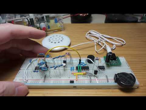
The circuit schematic and breadboard layout, including all the variations listed above:


Running on a breadboard with CR2032 3V coin cell supply. Note: here I’m using 3 x 270kΩ in place of the 820kΩ resistors (which I don’t have on hand).

Here’s a quick demo. I test a few things in the clip:
- light-sensitivity
- touch-sensitivity
- comparison to the original Simple Sound Effects circuit (by removing the second transistor)
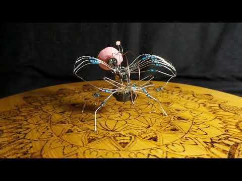
Freeform Build
The circuit must have been used in BEAM robots back in the day, so for this revival I decided to build a freeform “phototrope squawker”.
There was no grand design - it evolved in an ad-hoc manner as I put together the main subsystems:

The final result: some kind of robotic insect!
Credits and References
- this project on hackaday.io
- Greater Simple Sound Effects, Elektor May 1980, p21, by H. Thienel
- Simple Sound Effects, Elektor May 1979
- Simple Sound Effects 2.0 - elektor
- CD4040 datasheet
- CD4049 datasheet
- LDR 5539
- LM386 datasheet