
#870 LM386 Amplifier Module Kit
Building a common single-channel LM386 amplifier kit, with some modifications the the input wiring to support auxiliary bypass and mono inputs.
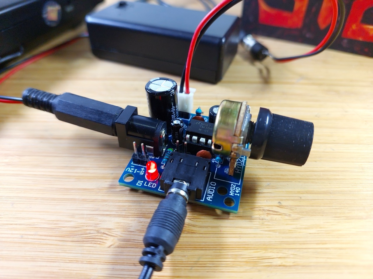
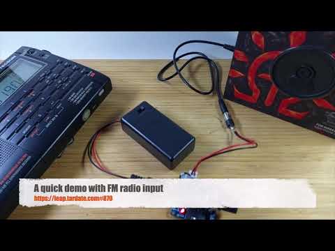
Here’s a quick demo..
Notes
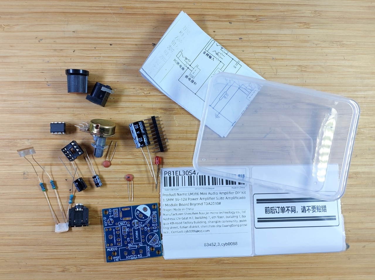
LM386-based amplifiers are easy to build, but they are also readily available as kits or modules. I’ve wanted to take a closer look at one of the kits to see if they yield any interesting secrets, so I purchased an example from SZFYDOSH Technology Store for SG$1.14 (Nov-2026): “LM386 Mini Audio Amplifier DIY Kit 3.5MM 3V-12V Power Amplifier Suite Amplificador Module Board Beyond TDA2030” (aliexpress seller listing)
The kit even comes in a little plastic storage box that will no doubt find a use in the workshop:
The LM386
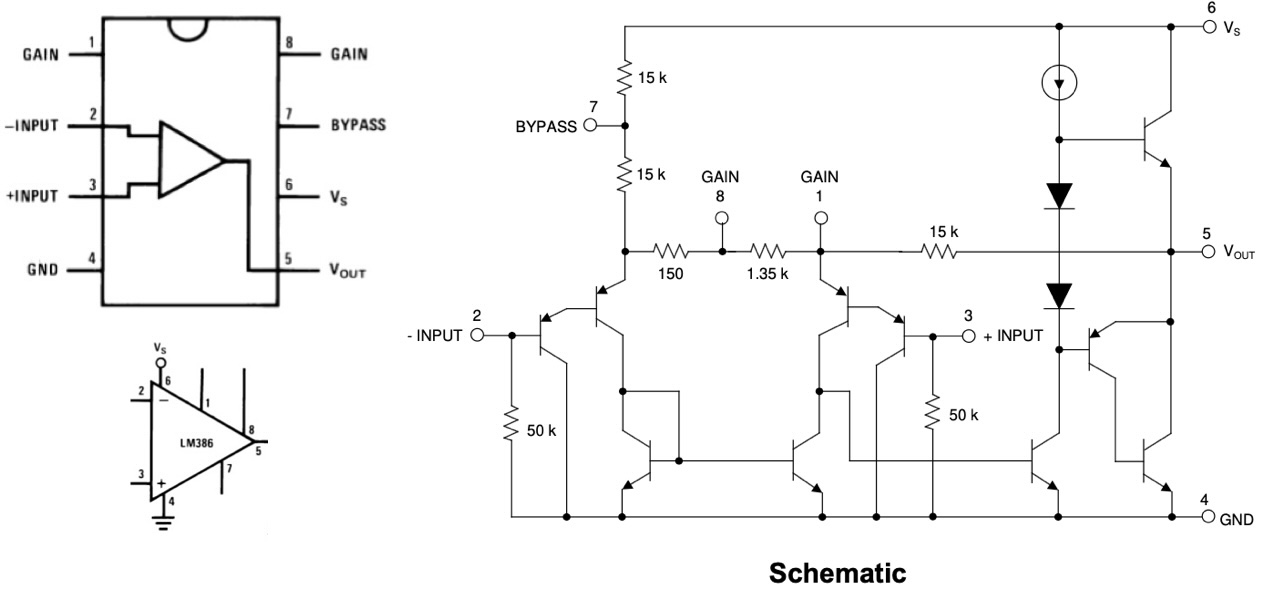
The LM386 is a low-voltage, low-power audio power amplifier integrated circuit, originally developed by National Semiconductor in the mid-1970s. It operates from a single power supply, typically between 4V and 12V, and requires very few external components to produce an audio amplifier with a typical output power of up to 0.5W. Its internally configured voltage gain is 20 (26dB). The chip incorporates internal biasing, thermal protection and a bypass pin for reducing power-supply and bias-related noise. With its low component count, small size and ease of use, the LM386 is widely used in battery-powered audio devices, small radios, intercoms, portable speakers and simple guitar practice amplifiers.
Kit Parts
| Ref | Qty | Part |
|---|---|---|
| R1,2 | 2 | 4.7kΩ resistor |
| R9 | 1 | 100kΩ pot |
| R9 | 1 | knob for pot |
| R10 | 1 | 4.7Ω resistor |
| C5,8 | 2 | 100nF ceramic capacitor |
| C6 | 1 | 100µF electrolytic capacitor |
| C7 | 1 | 10µF electrolytic capacitor |
| C9 | 1 | 1000µF electrolytic capacitor |
| D1 | 1 | 3mm red LED |
| J1 | 1 | 3.5mm stereo socket |
| J2,4,5 | 6 | 6 pin header (split to 3x2pins) |
| J3 | 1 | 5.5x2.1mm power socket |
| U1 | 1 | LM386M-91 |
| U1 | 1 | DIP8 socket |
| PCB | 1 | board |
Circuit Design
The circuit schematic is included in the kit instructions:
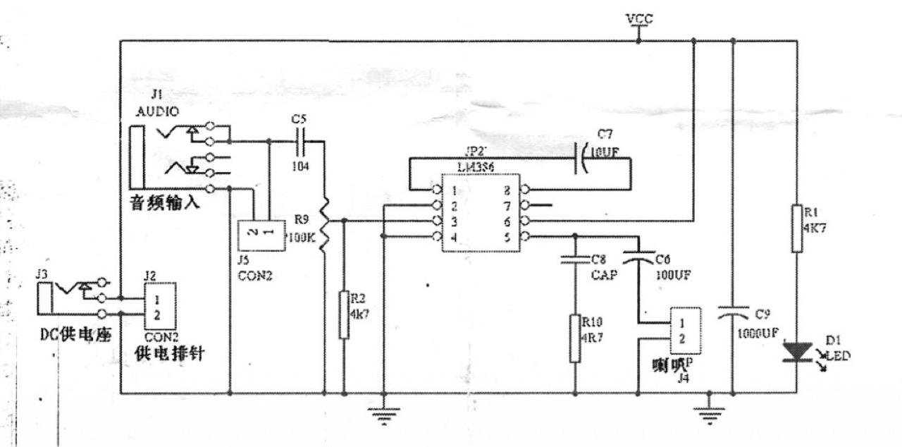
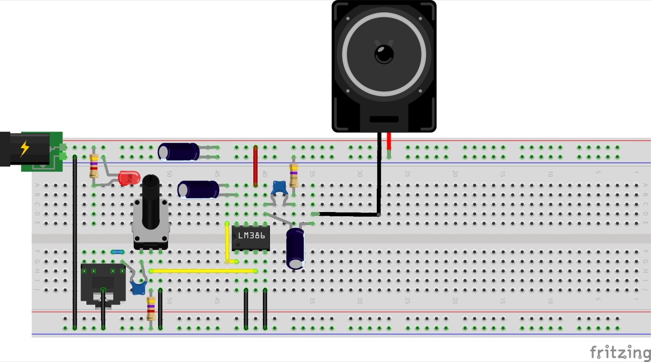
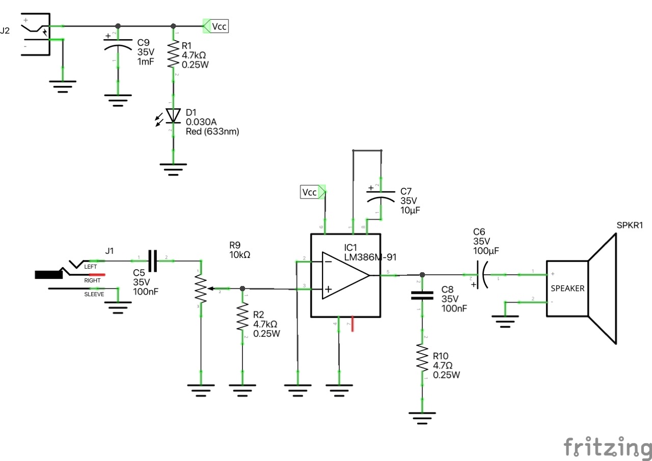
I redrew the circuit for clarity with Fritzing: see LM386ModuleKit.fzz.
The PCB
Before assembly, I luckily had a closer look at the PCB and noticed that the audio input jack could be connected in a better way.
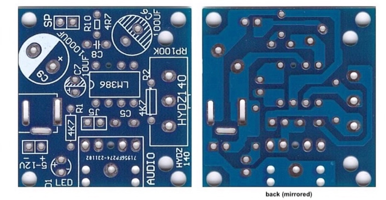
As designed, the J1 audio-in is tapped from the ring connector, and J5 is wired in parallel. While this will usually work, there are two issues:
- it won’t work with mono plugs since the audio tapped from sleeve and ring connectors. Mono plugs feed from tip and sleeve, with ring shorted to sleeve.
- J5 doesn’t work as an auxiliary input - both J5 and J1 remain connected to the audio chain, even if sources are connected to both inputs
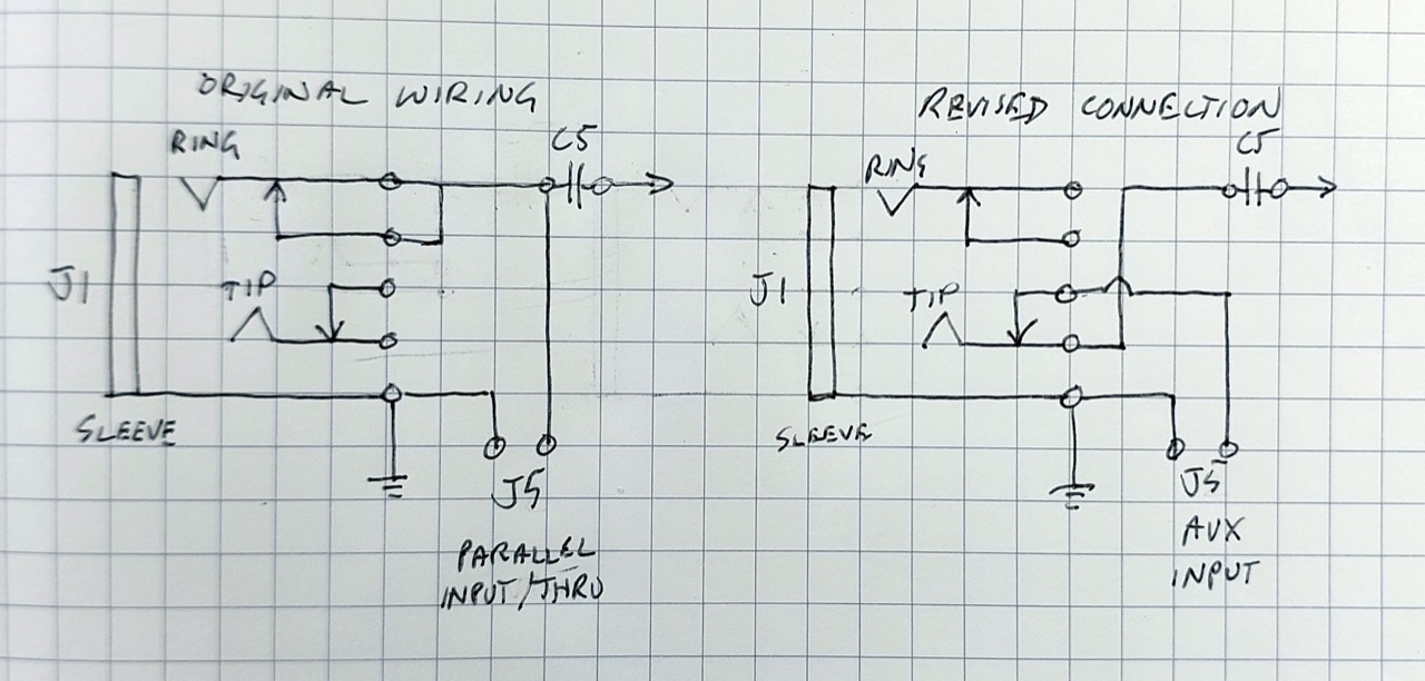
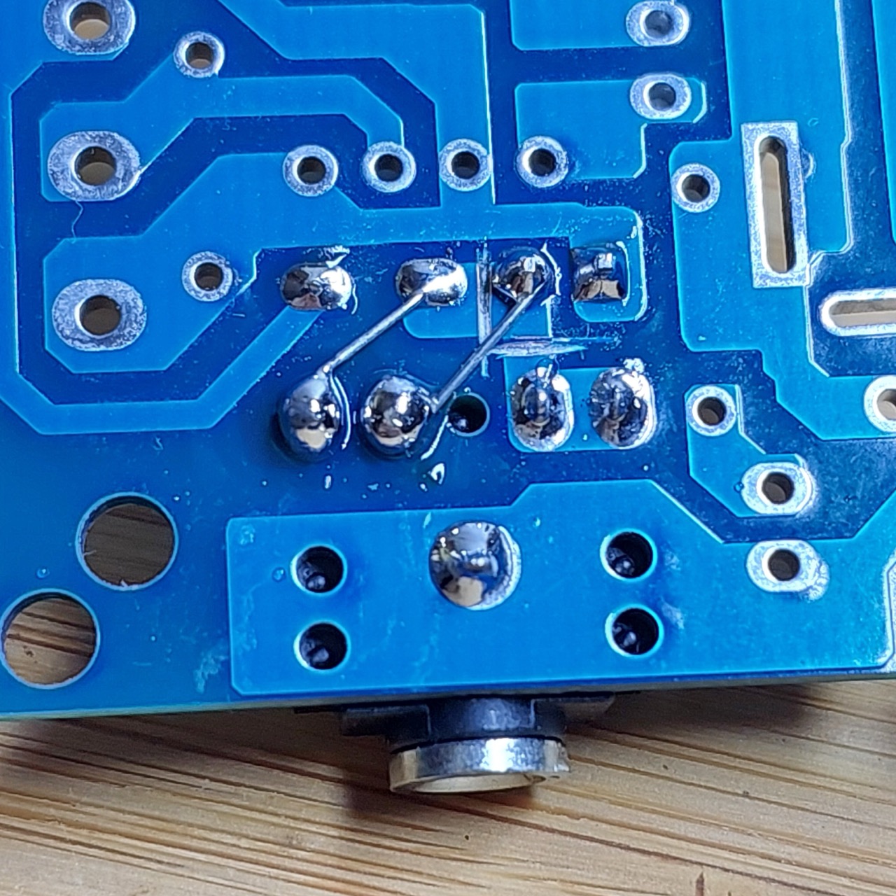
Before proceeding with the build, I re-patched the J1 and J5 inputs so they are more functional:
- audio-in is now tapped from J1 tip. This means it will work with both mono and stereo plugs.
- J5 is re-routed via the J1 tip by-pass connection. This allows it to function and auxiliary input. With an audio source connected to J5:
- it will drive the amplified while no plug is inserted into J1
- But if a plug is inserted into J1, it will disconnect J5 and drive the amp from J1 instead.
Construction
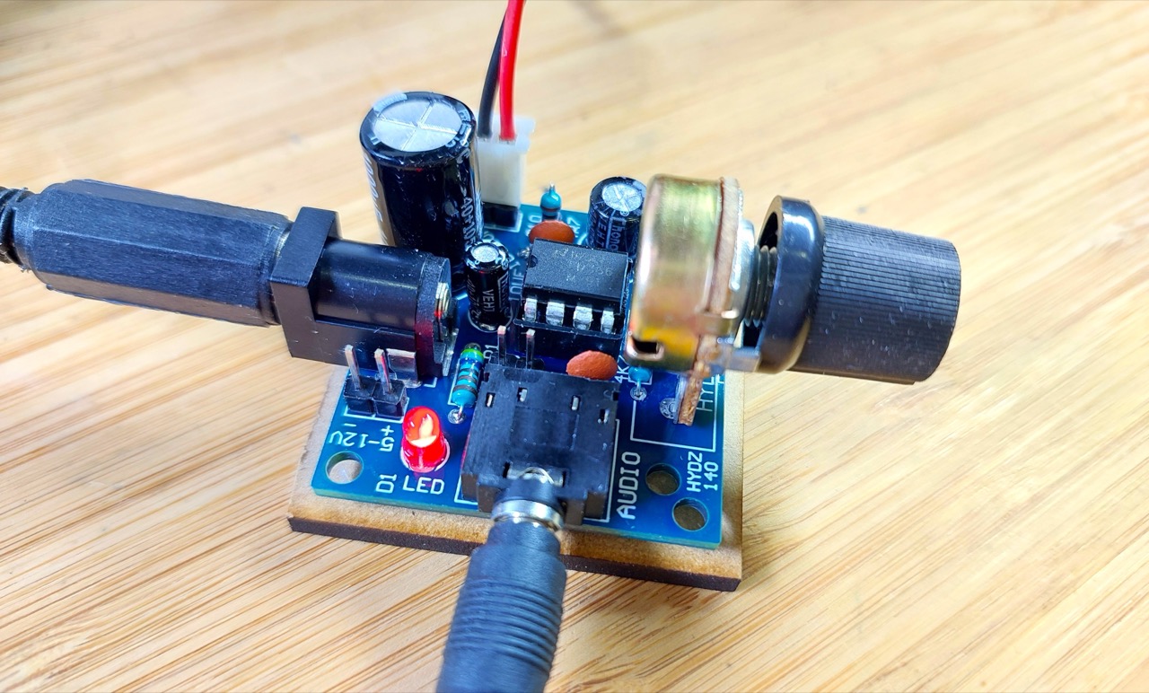
Construction complete:
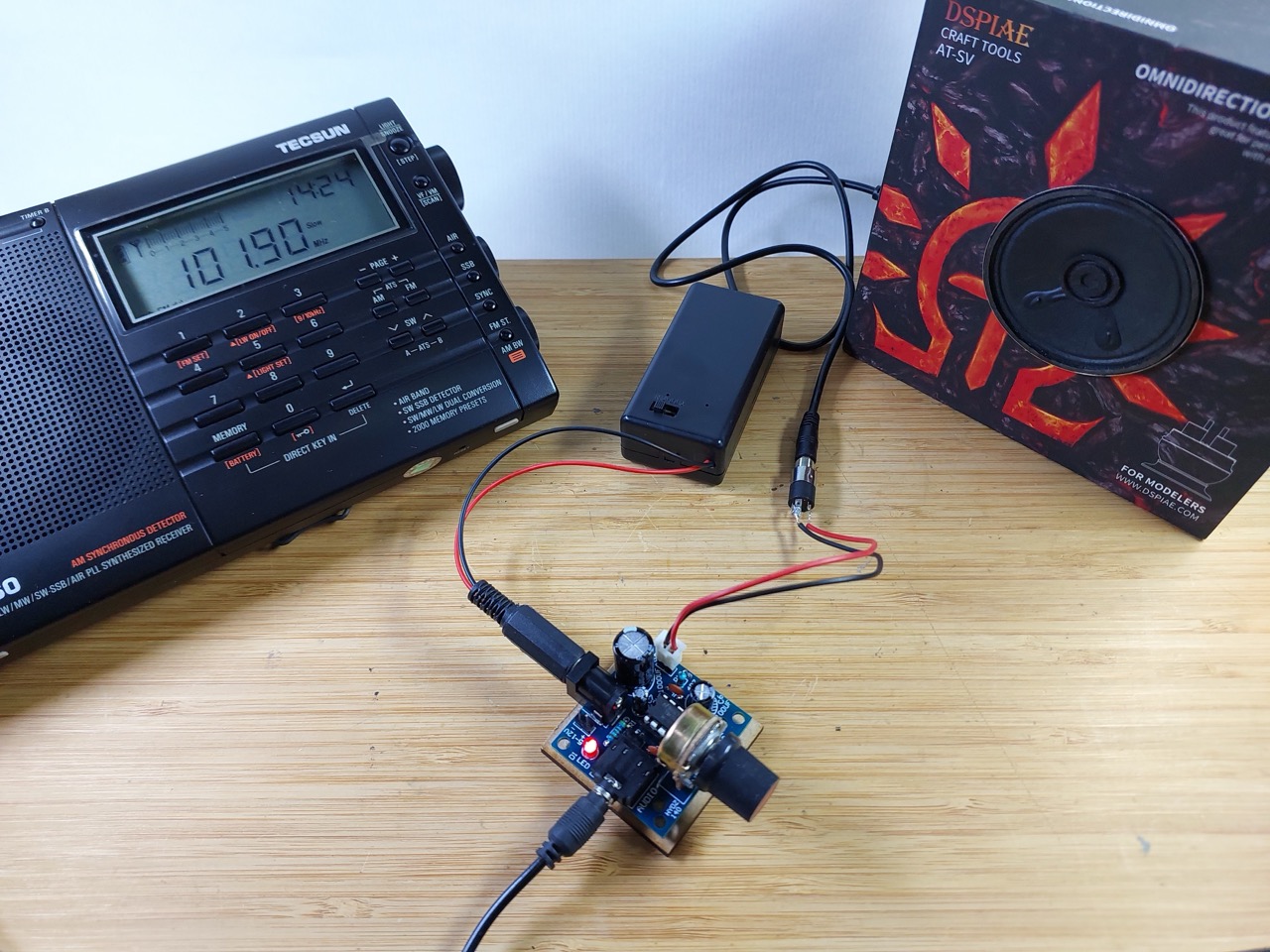
Under test .. and it works pretty well!
Credits and References
- “LM386 Mini Audio Amplifier DIY Kit 3.5MM 3V-12V Power Amplifier Suite Amplificador Module Board Beyond TDA2030” (aliexpress seller listing)
- Purchased from SZFYDOSH Technology Store for SG$1.14 (Nov-2026)
- See instructions
- LM386 Product Info - TI
- LM386 datasheet