
#682 Electret Sound Detection Module
Reverse-engineering a commercial electret sound detection module intended for use with an Arduino/microcontroller as a sound level trigger (not audio pre-amp).
Notes
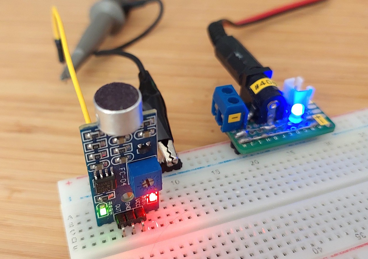
I bought a Sound Detection Sensor Module some time back. Similar modules are available from many sellers on the usual marketplaces (aliexpress, ebay, taobao).
I don’t think I’d be the first to think I was buying an electret audio pre-amp module, only to discover they are actually configured as binary sound level triggers.
Basically, this means that when the sound level goes above a configurable threshold, the input will go from LOW to HIGH.
The input would usually be connected to a microcontroller GPIO and be used for sound-activated trigger event.
NB: see LEAP#681 for coverage of a legit Electret Audio Pre-amplifier.
Module Specs
As given by one of the sellers:
Features:
- 100% Brand new and high quality
- Signal output indication
- Single channel signal output
- The output effective signal is low level
- When there is sound, output low level and the signal lights
- Can be used for Acoustic control light; give sound and light alarm working with Photosensitive sensor
Specifications:
- Size: approx.32mm17mm15mm(lengthwidthheight)
- Main Chip: LM393, Electret condenser microphone
- Working Voltage: DC 4-6V
- Color: Blue
- Net Weight: 3g
- Note: The Maximum induction distance is 0.5M
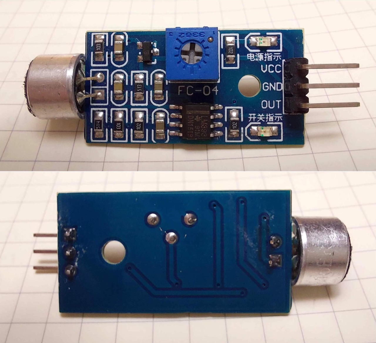
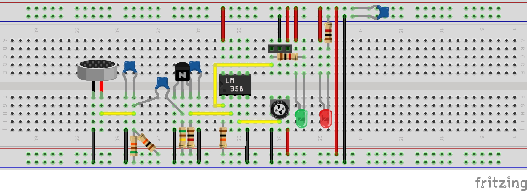
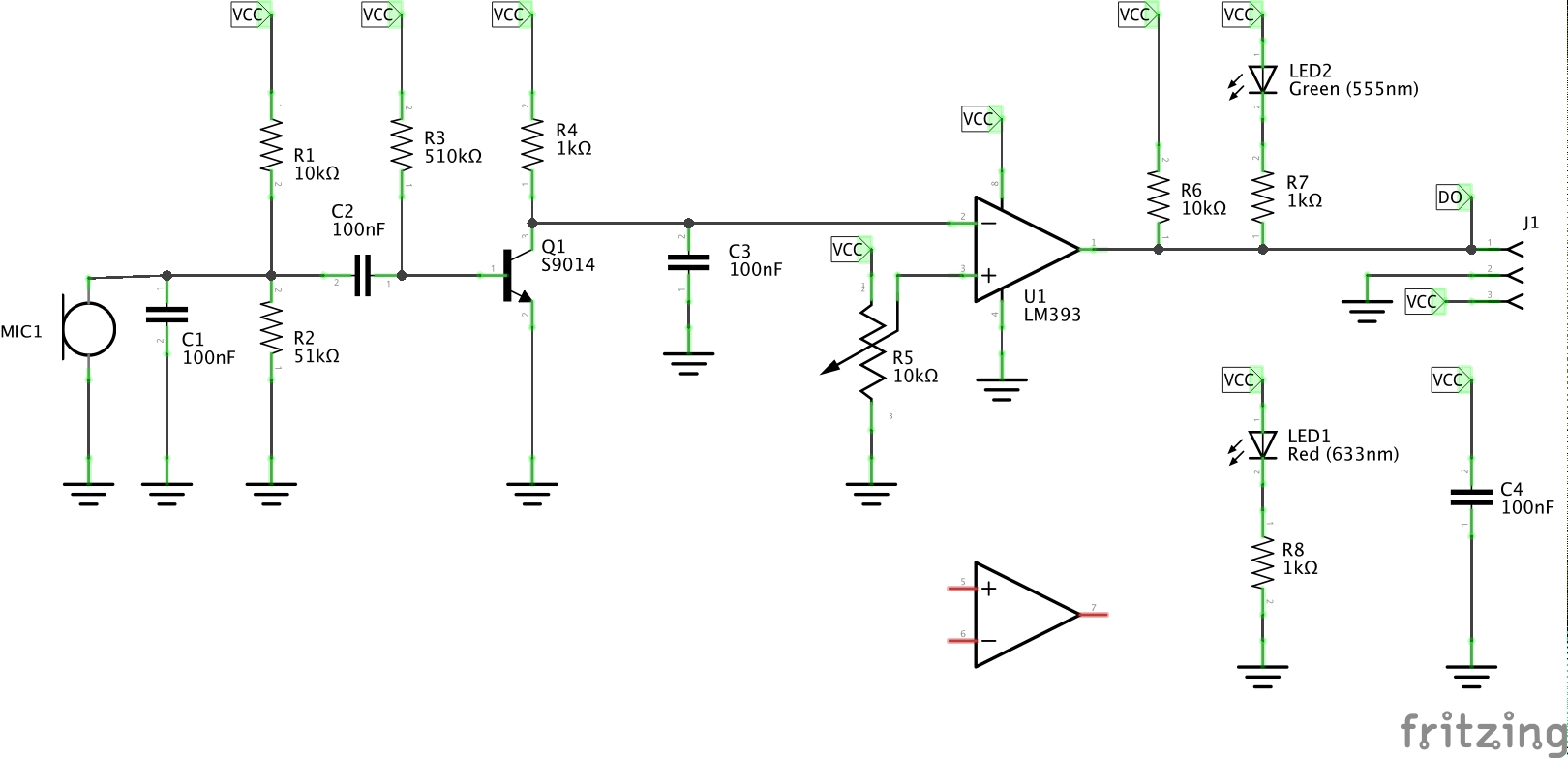
Circuit Design
Here’s my redrawing of the circuit. It basically comprises:
- electret input ac-coupled to S9014 common emitter amplifier
- amplified output (normally HIGH) is fed to inverting input of the LM393 comparator
- 10kΩ pot is used to set the comparator threshold (non-inverting input)
- the signal output is pulled HIGH by default R6, but is normally LOW when insufficient sound to trigger
- when the output is LOW, the green LED indicator will light
- a red LED is power indicator
Behaviour
The output is a rail-rail digital signal, suitable for connection toe a GPIO pin of a microcontroller.
The threshold level would be set so that any sound over a certain volume would cause the output to toggle. It is possible to adjust for both output orientations:
- adjust so normally output is high. Loud sound will cause the output to toggle high
- adjust so normally output is low. Loud sound will cause the output to toggle high
The trace below captures the module output when exposed to a pure 1kHz sine wave input sound. With the threshold set at just the right level, and given the input is a pure sine wave, the output is a square wave oscillating at the same frequency for each phase of the sound wave that exceeds the threshold
Credits and References
- Sound Detection Sensor Module Sound Sensor Intelligent Vehicle For Arduino
- S9014 datasheet
- LM393 Dual Differential Comparator