
#443 Interfacing 16x2 LCD with STM32F103C8T6
Using a 16x2 LCD with an ARM Cortex-M3 STM32F103C8T6 Blue Pill board and programmed the Arduino IDE.
This project was contributed by Naman Chauhan.

Notes
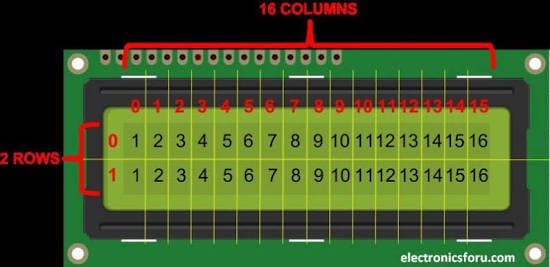
To establish a good communication between human world and machine world, display units play an important role. And so they are an important part of embedded systems. Display units - big or small, work on the same basic principle. Besides complex display units like graphic displays and 3D displays, one must know working with simple displays like 16x1 and 16x2 units. The 16x1 display unit will have 16 characters and are in one line. The 16x2 LCD will have 32 characters in total 16in 1st line and another 16 in 2nd line. Here one must understand that in each character there are 5x10=50 pixels so to display one character all 50 pixels must work together. But we need not to worry about that because there is another controller (HD44780) in the display unit which does the job of controlling the pixels.
Unlike normal development boards interfacing a LCD to a ARDUINO is quite easy. Here we don’t have to worry about data sending and receiving. We just have to define the pin numbers and it will be ready to display data on LCD.
Circuit Diagram and explanation
In 16x2 LCD there are 16 pins over all if there is a back light, if there is no back light there will be 14 pins. One can power or leave the back light pins. Now in the 14 pins there are 8 data pins (7-14 or D0-D7), 2 power supply pins (1&2 or VSS&VDD or GND&+5v), 3rd pin for contrast control (VEE-controls how thick the characters should be shown), and 3 control pins (RS&RW&E).
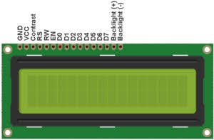
In the circuit, you can observe I have only took two control pins, this gives the flexibility. The contrast bit and READ/WRITE are not often used so they can be shorted to ground. This puts LCD in highest contrast and read mode. We just need to control ENABLE and RS pins to send characters and data accordingly.
In 16x2 LCD there are 16 pins over all if there is a back light, if there is no back light there will be 14 pins. One can power or leave the back light pins. Now in the 14 pins there are 8 data pins (7-14 or D0-D7), 2 power supply pins (1&2 or VSS&VDD or GND&+5v), 3rd pin for contrast control (VEE-controls how thick the characters should be shown), and 3 control pins (RS&RW&E).
In the circuit, you can observe I have only took two control pins, this gives the flexibility. The contrast bit and READ/WRITE are not often used so they can be shorted to ground. This puts LCD in highest contrast and read mode. We just need to control ENABLE and RS pins to send characters and data accordingly.In the circuit, you can observe I have only took two control pins, this gives the flexibility. The contrast bit and READ/WRITE are not often used so they can be shorted to ground. This puts LCD in highest contrast and read mode. We just need to control ENABLE and RS pins to send characters and data accordingly.
| LCD Pin No. | LCD Pin Name | STM32 Pin Name |
|---|---|---|
| 1 | Ground (GND) | Ground (G) |
| 2 | VCC | 5V |
| 3 | VEE | Ground (G) |
| 4 | Register Select (RS) | PB11 |
| 5 | READ/WRITE (RW) | Ground (G) |
| 6 | Enable (EN) | PB10 |
| 7 | Data Bit 0 (DB0) | No Connection (NC) |
| 8 | Data Bit 1 (DB1) | No Connection (NC) |
| 9 | Data Bit 2 (DB2) | No Connection (NC) |
| 10 | Data Bit 3 (DB3) | No Connection (NC) |
| 11 | Data Bit 4 (DB4) | PB0 |
| 12 | Data Bit 5 (DB5) | PB1 |
| 13 | Data Bit 6 (DB6) | PC13 |
| 14 | Data Bit 7 (DB7) | PC14 |
| 15 | LED Positive | 5V |
| 16 | LED Negative | Ground (G) |


Programming STM32 for LCD using Arduino
Uploading the Program to STM32F103C8T6 Board
Make the connections as show in the circuit diagram and use the code given below on Arduino IDE. Go to tools and make sure the right board is selected as done in getting started tutorial. Also, before uploading the program make sure the boot 0 jumper is set to 1 as shown in the image below and press the reset button. When the upload button is pressed is code should get uploaded and the message will be shown on LCD as show in the image below.
Verifying the Output on Operating Mode
As discussed in the above paragraph you should be able to notice the output as soon as the code is uploaded. But this program will not work the next time when you power up the board, since the board is still in programming mode. So once the program is uploaded the jumper on boot 0 should be changed back to 0 positions as show below. Also now since the program is uploaded to the STM32 board already we do not need the FTDI board and the whole set-up can be powered by the micro-USB port of the STM32 board as well as shown below.

This is just a simple interfacing project to help use the LCD display with STM32 board, but further you can use this to build cool projects. Hope you understood the tutorial and learnt something useful from it. If you had faced any problem in getting it to work, please use the comment section to post the problem or use the forums for other technical questions.
Verification Build
A second build with a few variations:
- using a CH340G instead of FTDI serial interface
- 220Ω current limiting resistor added to the LED supply lines
All good:

Credits and References
- ARM Cortex-M3 STM32F103C8T6 Minimum System Development Board STM32 - example from a seller on aliexpress
- STM32F103C8 Product Info and Datasheet
- LEAP#749 HD44780-based LCD Modules (e.g. QC1602A)