
#394 AT89C2051 Programmer
Building a programmer for the Intel MCS-51/8051 compatible AT89C2051, with host software running on macOS. Originally tested with Intel-based macOS, but now updated for Apple Silicon.
Notes
I’ve been meaning to dive a bit deeper into Intel MCS-51/8051 devices and programming ever since I built the LEAP#088 ElectronicClockKit. While it’s long been EOL at Intel, this article By Jon Wilder is a valiant argument for why they are still around.
I have some (still in production) AT89C2051 chips - but before I can do much more, I need a programmer.
Reading the AT89C2051 datasheet, its seems programming is actually a quite straight-forward process - the only complication being the need for a 12V programming voltage in addition to standard logic high of ~5V.
So while I could go out and buy a programmer, the idea of building my own is very attractive for two reasons:
- it is a bit of a short cut to building familiarity with the chip and datasheet
- I can make sure it supports my host platform of choice - macOS
Inspirations and Prior Art
I found a couple of interesting projects that provided a good starting point. I’d recommend checking these out. In summary:
- AT89C2051_programmer
- by piotrb5e3
- uses separate 12V programming voltage power supply [negative]
- open source python host programming software distributed via PyPI (at89overlord) [positive]
- uses Arduino Uno as a programmer [positive]
- An Arduino-based programmer for the AT89C2051 chip
- by ceptimus
- uses a charge pump for 12V programming voltage [positive]
- charge pump control is quite naive (bit-banging) [negative]
- C# host programming software, open sourced but not in collaborative version control [negative]
- uses Arduino as a programmer [positive]
- quite wasteful of GPIO pins, so requires Arduino Mega/ATmega2560 [negative]
Boiling down my wishlist/plan:
- use an Arduino-controlled charge pump for programming voltage, but control it with PMW similar to LEAP#392 Dickson Charge Pump
- assign GPIO pins judiciously so can still use Arduino Uno/ATmega328 as the programmer
- base the Arduino programming sketch on piotrb5e3’s, but modified for charge pump control
- hopefully maintain compatibility with at89overlord so it can be used as the host programming software, else adapt as required
VPP/RST Power Control
We need to switch between 12V, 5V and 0V on the VPP/RST pin for the range of programming modes. From the datasheet
- VPP Programming Enable Voltage: 12V ± 0.5V (programming current is only 250µA)
- for HIGH with 5V supply: actually require 0.7 * VCC i.e. 3.5V minimum
- for LOW: actually require 0.2 * VCC - 0.1V i.e 0.9V maximum
My goal was to achieve this with as few Arduino pins as possible, and without requiring an external 12V power supply. I can’t find the specs, but I’m pretty sure we need negligible current/power at any of these levels, which simplifies things.
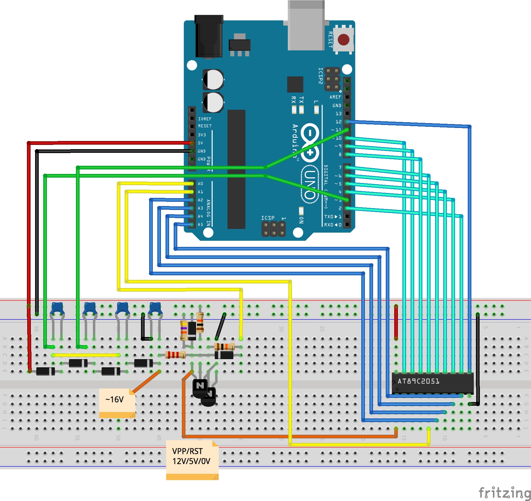
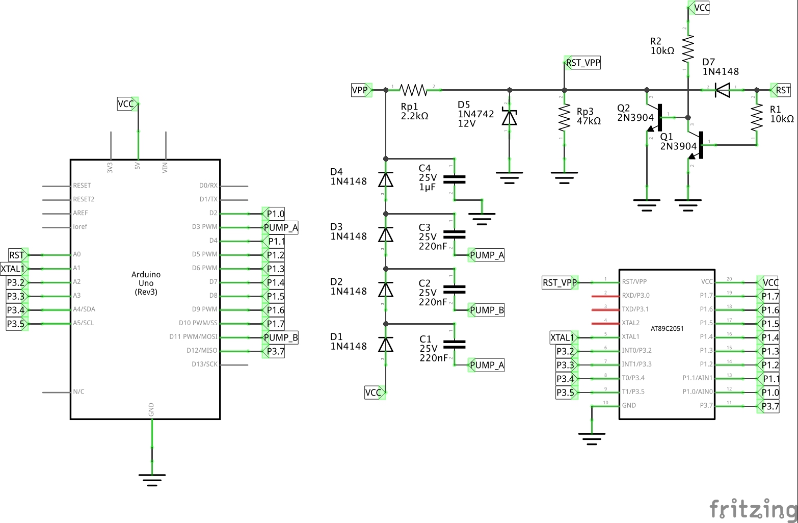
I finally figured out this scheme. It needs 3 Arduino pins:
- ~16V charge pump, generated with 62kHz PWM from 2 pins (inverted pair of PWM waves)
- the output is fed to VPP/RST after clamping with a 12V zener diode
- 0/5V controlled with a digital pin:
- 5V is connected to VPP/RST via a diode to prevent 12V appearing back on the Arduino pin
- 0V signal is inverted via a pair of NPN transistors that pull the VPP/RST down hard
- this avoids ~2V from the unexcited charge pump preventing a true 0V input
And it works;-)
There is one caveat: there’s an “invalid state” that must be avoided lest the magic smoke may be released in a possible high current/burnout. This is avoided in the programming software.
Here’s a breakdown of the control states. In this table:
- RST_PIN - pin A0 output
- Charge Pump PWM - pins 3,11 output
| RST_PIN | Charge Pump PWM | Charge Pump Voltage | Q1c | Q2 | VPP/RST |
|---|---|---|---|---|---|
| High, 5V | On | 12V | Low | Off | ~12V |
| Low, 0V | On | 12V | High | On | invalid state |
| High, 5V | Off | ~2V | Low | Off | ~4.4V |
| Low, 0V | Off | ~2V | High | On | ~0V |
Possible improvement: I could probably reduce this to requiring 2 pins in total with the addition of an inverter IC to:
- invert a single PWM signal for charge pump control
- replace the 2 x NPN inverter for the 0V pull-down
The Programmer.ino sketch includes all the necessary VPP/RST Power Control.
Installing at89overlord
Using a Python3 virtual environment. Requirements are in requirements.txt
python3 -m venv venv
source venv/bin/activate
pip install --upgrade pip
pip install -r requirements.txt
This installs at89overlord 0.4.0 (there was a minor issue with the packaging of 0.3.0 that may cause problems; 0.4.0 works fine though)
Programming a Device
On my system, I have the Arduino plugged in and appearing on the following devices:
$ ls -1 /dev/*usb*
/dev/cu.usbserial-2420
/dev/cu.wchusbserial2420
/dev/tty.usbserial-2420
/dev/tty.wchusbserial2420
The Programmer.ino sketch is first uploaded to the Arduino. This sets it up in programmer mode, waiting for programming commands.
Using the hex file generated with the LEAP#394 AT89C2051 Blinky code here, programming a chip is as simple as this:
$ at89overlord -p /dev/tty.usbserial-2420 -f ../Blinky/src/Blinky.hex
# Initializing the programmer...
# Initialized!
# Confirming chip ID...
# Confirmed!
# Erasing flash...
# Done!
# Writing flash...
# Done!
# Verifying...
# Done!
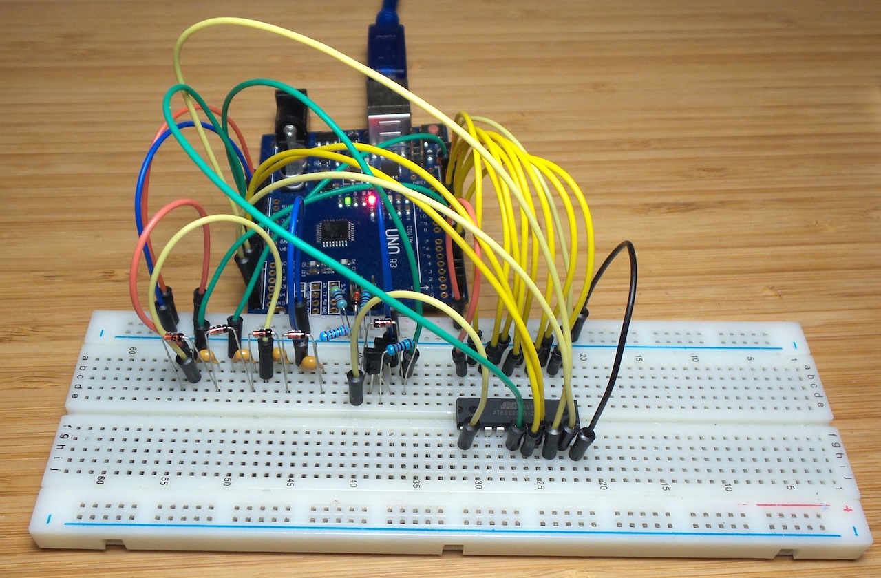
Breadboard Construction
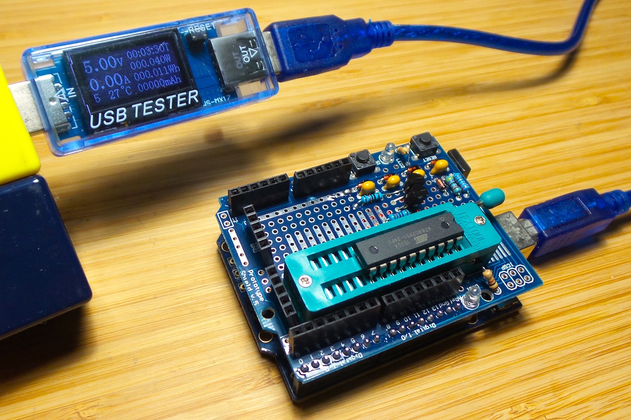
Putting it on a Prototyping Shield
With so many wires on the breadboard, this is not very practical to build every time I need to program an 8051, and it is pretty fragile - just one dodgy wire and programming/verification can easily fail.
It looks like a nice project to build a custom board, with ATmega328 built in … another project for later!
I have a spare prototyping shield for an Uno, so for now I’ve put the circuit on that. Here’s a sketch of the layout I used:
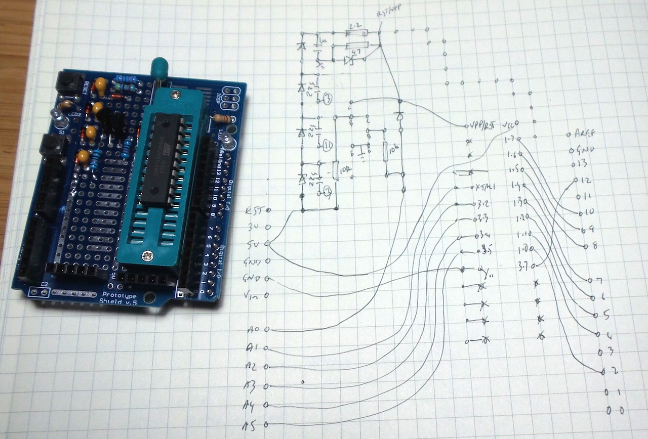
The finished shield:
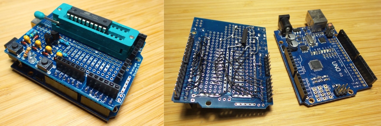
Now it’s easy to program an AT89C2051..
Just Using a 12V Supply?
Steve Schnepp has posted about a neat alternative: Simple AT89C2051 programmer with Arduino.
This takes advantage of the Arduino Uno R3 design feature that if 12V supply is plugged into the power jack, then 12V is available on VREF, and one can do away with the charge pump. A board design is on the way.
Credits and References
- LEAP#394 AT89C2051 Blinky
- LEAP#392 Dickson Charge Pump
- LEAP#088 ElectronicClockKit
- Intel MCS-51
- Intel’s MCS-51 Microcontroller Family – It’s Here to Stay by Jon Wilder
- AT89C2051 product info and datasheet
- 12 Volt Arduino-based Charge Pump - similar project used as inspiration
- AT89C2051_programmer
- An Arduino-based programmer for the AT89C2051 chip - ceptimus
- ..as mentioned on my blog