
#793 AT89C2051 7-Segment LED Control
Driving a common-cathode 7-Segment LED with the AT89C2051.

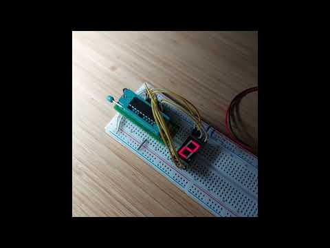
Here’s a quick demo..
Notes
I am using a common cathode 7-segment LED similar to the SC56-11 (see the datasheet).
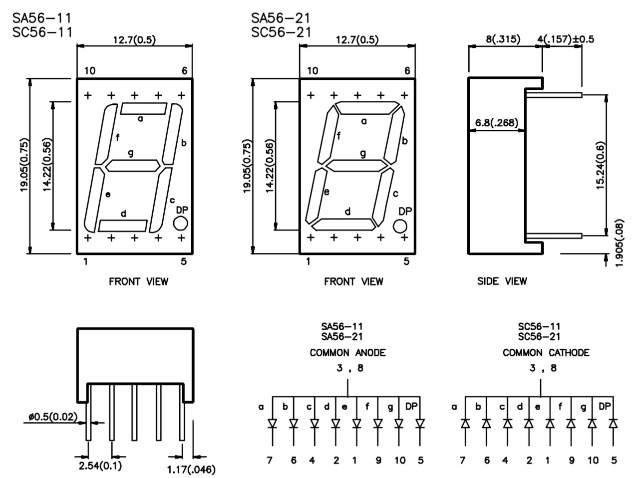
Segment-Pin Mapping
Here’s a summary of how port bits are mapped to LED segments:
| Port | LED Pin | Segment |
|---|---|---|
| P1_0 | 7 | A - top horizontal |
| P1_1 | 6 | B - top right vertical |
| P1_2 | 4 | C - bottom right vertical |
| P1_3 | 2 | D - bottom horizontal |
| P1_4 | 1 | E - bottom left vertical |
| P1_5 | 9 | F - top left vertical |
| P1_6 | 10 | G - center horizontal |
| P1_7 | 5 | dp - decimal point |
Character Encoding
With a common-cathode device, a port bit needs to be asserted for the corresponding segment to light. If a common-anode LED is used, the port bit needs to be low for the segment to light i.e. it is the bitwise complement of the common-cathode value.
| Character | P1 (common cathode) | P1 (common anode) |
|---|---|---|
| 0 | 0b00111111 | 0b11000000 |
| 1 | 0b00000110 | 0b11111001 |
| 2 | 0b01011011 | 0b10100100 |
| 3 | 0b01001111 | 0b10110000 |
| 4 | 0b01100110 | 0b10011001 |
| 5 | 0b01101101 | 0b10010010 |
| 6 | 0b01111101 | 0b10000010 |
| 7 | 0b00000111 | 0b11111000 |
| 8 | 0b01111111 | 0b10000000 |
| 9 | 0b01101111 | 0b10010000 |
Demo Circuit Design
Designed with Fritzing: see Led7SegmentControl.fzz.
With the AT89C2051, Port 1 is an 8-bit bi-directional I/O port. Port pins P1.2 to P1.7 provide internal pull-ups. P1.0 and P1.1 require external pull-ups. The Port 1 output buffers can sink 20 mA and can drive LED displays directly.
With a common-cathode LED display:
- the internal pull-up resistors on P1.2 to P1.7 provide a suitable drive current for an LED segment. They do not require additional external pull-up or current limiting resistors.
- P1.0 and P1.1 require an external pull-up to drive the LED segment. Using 10kΩ appears to provide a similar drive current to the pins with internal pull-ups
Note that if using a common-anode LED display, current limiting resistors will need to be added for the LED segments. The code has a setting to flip between common-anode and common-cathode logic.


The Code
It uses a timer to increment the digit written to the LED display every second.
Programming
The src/Makefile is setup to compile the code using the SDCC compiler .. running on macOS in this instance:
$ cd src
$ make
sdcc -mmcs51 --code-size 2048 Led7SegmentControl.c -o Led7SegmentControl.ihx
packihx Led7SegmentControl.ihx > Led7SegmentControl.hex
packihx: read 20 lines, wrote 29: OK.
Program the chip using at89overlord and
the LEAP#394 AT89C2051 Programmer:
$ at89overlord -p /dev/tty.usbserial-2420 -f ./Led7SegmentControl.hex
# Initializing the programmer...
# Initialized!
# Confirming chip ID...
# Confirmed!
# Erasing flash...
# Done!
# Writing flash...
# Done!
# Verifying...
# Done!
Testing
I have the circuit setup on a breadboard with the LEAP#780 AT89C2051 Breadboard Adapter:
