
#570 MT3608 on a Breadboard
A quick breadboard test of the canonical MT3608 switch mode power supply boost converter circuit.

Here’s a quick demo..
Notes
The MT3608 (parts also produced as the B6286) is a very efficient boost converter that can deliver up to 24V at 4A. It requires only 6 external passive components, and is readily available as a complete module for as little as $0.40.
In this project, I’m simply building the standard variable converter circuit on a breadboard to verify its performance.
MT3608
- 2V to 24V Input Voltage
- 1.2MHz Fixed Switching Frequency
- Internal 4A Switch Current Limit
- Internal Compensation
- Up to 28V Output Voltage
- Automatic Pulse Frequency Modulation Mode at Light Loads
- up to 97% Efficiency

Circuit Layout
The M3608 comes in a miniscule SOT23-6 package (0.95mm pin spacing). I’ve put it on a SOT23-10 DIP adapter board for use on a breadboard.
Supporting Component Selection
Inductor
The datasheet recommends a 4.7µH to 22µH inductor with low core loss at 1.2MHz. I’m using a 22µH CDRH104R SMD power inductor.
Filter Capacitors
22µF input and output ceramic capacitors are recommended. I’m using SMD 22µF ceramics mounted on a DIP adapter board.
Diode Selection
A low forward-voltage schottky diode is recommended. I’m using 1N5819 SMD mounted on a DIP adapter board.
Feedback Resistors
The feedback voltage-divider with two resistors establishes the output voltage level where Vref is 0.6V:
Vout = Vref * (1 + R1/R2)
I’m using R1 = 100kΩ variable resistor (“rheostat” wiring), and R2 = 2.2kΩ.
This give a theoretical maximum output voltage of 27.9V.
The theoretical minimum output voltage is 0.6V however in practice the lowest output voltage is limited to around 1 diode drop less than the input voltage, hence there is a bit of dead zone at the lower adjustment.
Note: some boards/schematics will wire the R1 variable resistor in a potentiometer configuration, with the wiper connected to the FB pin. The same principle applies, however the voltage divider calculations of course change.
WARNING: this configuration is only really safe if the input voltage is below about 7V, since otherwise it is possible to push the FB pin beyond the rated 6V when R1 is turned to the extreme. See LEAP#642 MT3608 Safe Control for an alternative that is safe for higher input voltages.
Enable Pin Connection
I’ve chosen not to use this in this build, so it is pulled high to the input power rail (always enabled).
Construction


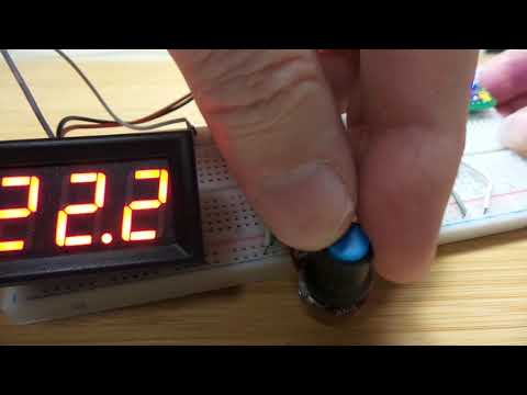
Testing on a breadboard with 5V input and a panel meter to display the boosted output:
